What's new
Van's Air Force

Don't miss anything! Register now for full access to the definitive RV support community.

"In the works!" carbon wing root fairings

Cfrisella

Well Known Member
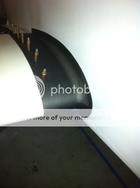
This another item I'm working on. I got the passenger side wing root fairing trimmed and fitted today. It went on really nice! I got to give Van's some credit though. All design dimensions where taken right off our build plans. I just scaled them up and built them in SolidWorks. It will probably be a month until I can do the pilot side, but I'll keep you posted as they progress.

1329448899.jpg
 
tips and fairings

Any testing on the wing tips, do you gain any speed with them and does stall speed increase. I suppose it would. The new fainings look great.
 
test airspeed impact carefully...

There is a similar fiberglass product that is out there that looks great but I recall reading reports indicating a surprising reduction in top end airspeed... the most effective aerodynamic connection appears to be from the simple 90 degree interface as designed.
 
In the works!

Chris how about a NACA duct with a 4" outlet to supply air to an oil cooler? That would reduce the air taken from the engine for cooling.

Brian
 
Corrosion?

Hmm. Is there some sort of coating on the carbon fiber that prevents it from reacting to aluminum?

From what I recall of my high school chemistry, carbon and aluminum will for a natural anode that would break down the aluminum over time.

Just curious.

-Matt
402BD
 
Corrosion

Makes sense. The photos on the web site however show bare carbon installed on the aircraft. I really like the look so it'd be a shame to cover it up with paint.

Maybe a clear coat?

-Matt
402BD
 
Epoxy

There shouldn't be any carbon in contact with the aluminum, it's encased in epoxy. Should provide as much or more of a barrier as paint would.

Just curious - don't those clecos go into the fuel tank???
 
Last edited:
Look great!

Hard to imagine how those could slow the plane down. Testing will tell -- there's lots of folks that cite the mythological draggy fairings, but I've never actually seen anything on them other than hearsay.

At cruise with low lift coefficients, the fairing doesn't matter much. The perpendicular junction works fine. Not to say a good fillet might not be slightly better.

At high altitude, or high G's like turning pylons, a good fillet is going to make a big improvement. Look at the wing junction fairings on most WW II fighters.
Its in the corners where the energy is lost, so that's what they focused on. The fairings were a big improvement.
 
There shouldn't be any carbon in contact with the aluminum, it's encased in epoxy. Should provide as much or more of a barrier as paint would.

In theory that might be true, but in practice I wouldn't rely on it. I always use a thin veil ply of fiberglass, usually around 5oz, wherever I expect to bond or fasten carbon to metal parts.

I also never ever laminate raw carbon fiber onto metal parts. Steve Smith can tell you a story about an aluminum sailboat boom reinforced with carbon that split wide open in only a handful of days from the force of the aluminum oxide powder that was building up between the carbon and the aluminum.

One other data point I can offer is that I once tried to make a styrofoam hotwiring bow out of a stick of carbon fiber pultrusion. I thought that the carbon fibers would be adequately insulated by the resin that binds the fibers of the pultrusion, so I just tied each end of the wire to the carbon. However, the bow did not work right until I insulated one of the ends of the wire from the bow. It turned out that the carbon conducted enough electricity to prevent the wire from heating up.

That relatively low resistance suggests to me that, for pultrusions at least, there is strong potential (get it?) for galvanic corrosion with other metals such as aluminum and steel. The pultrusions have a pretty high fiber/resin ratio, but not extremely high, so I think there is also the possibility for this kind of reaction with other carbon products that are supposedly encased in resin.

Thanks, Bob K.
 
Interesting

Bob,

That's interesting. Do you think a layer of paint or two would be sufficient? Or brushing on additional epoxy then the piece comes in contact with the aluminum?

Tom
 
I know there's some debate wether or not the wing root fairings slow the plane down. We'll have to see about this one. I did make the radius to the fuse pretty small.

I'd never mount carbon directly to aluminum. The airplane is painted, the carbon part has a matte clear coat and then you still have the barrier created by the resin. It's very easy to coat the back of any part for added insurance though.

The Clecos don't go into the tanks.
 
Bob,

That's interesting. Do you think a layer of paint or two would be sufficient? Or brushing on additional epoxy then the piece comes in contact with the aluminum?

Tom

Tom, it might be sufficient, but only if there is absolutely no rubbing or fretting that abrades through the paint. When the paint goes away, the interface between carbon and aluminum becomes a battery (galvanic cell on oldspeak). I know that carbon floor panels in airliners have been a maintenance headache where the contact patches abraded through to allow carbon-aluminum contact.

That is why I use a fiberglass insulating ply between carbon and aluminum. A relatively thin layer, like 5oz, is probably all that is needed. Even a 3oz veil cloth like Style 120 might suffice; and with good brush work it would be all but invisible against the carbon.

Thanks, Bob K.
 
How about using a strip of the same tape we use on the flaps?
You would need to poke some holes in it for the screws tho-
 
I built the wing tips to require a 3 mil strip of some buffer between the tips and wing. I used polyethylene 1/2 inch tape from mcmaster Carr. It's also helps because the wing dimples are a little deeper then the wing tip shell and they wouldn't sit flush. A good separator for corrosion reasons as well.
 
There is a similar fiberglass product that is out there that looks great but I recall reading reports indicating a surprising reduction in top end airspeed... the most effective aerodynamic connection appears to be from the simple 90 degree interface as designed.

My first reaction was ''very nice" (still is), and thought of the speed thing immediately. Had the same thought as Stephen (based on some discussions with Rocket guys that tried and discarded larger wing root fairings), though I did note these look like a nice tight fit. Then I read on...

Hard to imagine how those could slow the plane down. Testing will tell -- there's lots of folks that cite the mythological draggy fairings, but I've never actually seen anything on them other than hearsay.

At cruise with low lift coefficients, the fairing doesn't matter much. The perpendicular junction works fine. Not to say a good fillet might not be slightly better.

At high altitude, or high G's like turning pylons, a good fillet is going to make a big improvement. Look at the wing junction fairings on most WW II fighters.
Its in the corners where the energy is lost, so that's what they focused on. The fairings were a big improvement.

Steve, you definitely have my attention (thus so do these fairings ;)). I remember the discussion from Aero 101 on interference drag, and have been surprised by the discussions that the 90 deg on our planes is less draggy than a fillet. Perhaps this type of fairing (small radius) would be a good solution for both SARL and pylon racing (like I said, you piqued my curiosity).

I know there's some debate wether or not the wing root fairings slow the plane down. We'll have to see about this one. I did make the radius to the fuse pretty small.

I'd never mount carbon directly to aluminum. The airplane is painted, the carbon part has a matte clear coat and then you still have the barrier created by the resin. It's very easy to coat the back of any part for added insurance though.

Really nice looking Chris..well done. If ya need a beta tester that races straight and turning races, and likes to test for speed, I'd volunteer! (Doesn't have to be gratis either!) I have lots of paint on the interface areas too! :D

Interesting discussion on the conductivity and corrosion issues Bob. Guess I better plan some mitigation measures on the plenum to baffle interface!! (Thanks!)

Cheers,
Bob
 
layer of glass for alum contact areas

recommend to have a layer of glass where in contact with alum to prevent galvanic corrosion. looks like a nice product.
 
Couple of things

1) Fairings etc has wing root fairing for the 6/7 and I believe 8. Robbie Attaway flew them and did not find any quantifiable gains. So, to avoid any disappointment, consider such fairings "bling" for the plane.

2) With carbon panels the chance of actual carbon coming in contact is slim due to the resin/epoxy layup. With years of wear, possibly.

3) Anywhere where we would use carbon is most likely aesthetic and not structural. On my current 7 I have a carbon overlay panel. It is fastened to the aluminum panel with platenuts and screws. The holes are oversized by a couple of thousands. FYI, it is two layers of glass and two layers of carbon. Done for cost not any concern for corrosion. For the carbon wing tips, oversized holes will handle the dissimilar materials.

Keep in mind, carbon is structurally very good. However, it is very brittle and doesn't handle abrasion potential very well. Would not be good for wheel pants for example.
 
Read my report

on speed mods. I had fiberglas intersection fairings on my RV6 and was told that they created a sizable amount of drag. They did have a more pronounced curve where they intersected the fuselage than what is shown in the carbon fiber photos. I removed the fairings, installed Van's plan intersection fairings with the rubber fillet and gained 8 knots over the ground. The rule is if the intersection has a 90 degree angle do not fair it with a curved surface. Take a look at fast military fighters. No fairing. That being said, if the carbon fiber could be constructed with a sharp angle at the intersection, it would be perfect, IMHO. The rubber is kind of a challenge to insert when it is new. I would also suggest that it rise no more than 1" against the fuselage so that it would not have to be screwed in to avoid vibration from the slipstream.
 
Not likely the wing root will make much difference either direction. Most commercially produced wing roots are substantially larger and extend much more both forward and aft than you see on GA aircraft. The good looking Wing Root for the Rockets do almost nothing for top speed but increase the stall by a few knots. See:

1223520614.jpg


AA757.jpeg


photo.show
 
I once saw the RV-4 with retractable gear.
The gear retracted inward, forward of the spar, so a triangular leading edge extension was made to house the wheel.
I wonder what effect that has on stall and accelerated stalls like aerobatics and other forms of yanking and banking?
Especially relating to the RV-8 and the main gear root interupting the airflow at the wing root at high angles of attack?
SO I guess I'm asking if anyone has an opinion on leading edge root extensions, and if a root fairing could incorporate a small one?
A Pull from Wiki:
Leading edge root extensions (LERX) are small fillets, typically roughly triangular in shape, running forward from the leading edge of the wing root to a point along the fuselage. These are often called simply leading edge extensions (LEX), although they are not the only kind. To avoid ambiguity, this article uses the term LERX.

On a modern fighter aircraft they provide usable airflow over the wing at high angles of attack, so delaying the stall and consequent loss of lift. In cruising flight the effect of the LERX is minimal. However at high angles of attack, as often encountered in a dog fight, the LERX generates a high-speed vortex that attaches to the top of the wing. The vortex action maintains a smooth airflow over the wing surface well past the normal stall point at which the airflow would otherwise break up, thus sustaining lift at very high angles.
 
Last edited:
As I recall from discussions a number of years ago (no data - call it anecdotal), the talk of draggy intersection fairings comes not from the general fillet, but from a large wing/body fairing at the trailing edge. Those large wing/body/flap fairing that you see on modern biz-jest look cool to some folks, but they don't do us any good at our speeds.

I am interested to hear that "Woodman" documents a speed loss from fairings - my question is if they had a significant flap fairing at the back end.

I am not really satisfied with the aluminum fairings on our RV-3 ( those on the -6 and -8 fit great - the ones on the -3, not so well...), and have thought about doing a fiberglass fillet. Have to decide before it goes to paint though!

Paul
 
All this conversation about using carbon fiber on aluminum now has me concerned. I used carbon fiber for attaching the front portion of the canopy in my tip up. Although it was first filled with a layer of flux and then the curve was made using a few layer of CF, of course as always I dress the part with a coat of resin first before applying the material but that was mostly for a better adhesion.

I wonder if/how I can detect any sign of corrosion since it has been painted and nothing shows so far (3 years flying). I guess one advantage in my case is that there is no relative movement.
 
There is a company that made carbon fiber prop spinner bulkheads for several Piper models, and had some corrosion issues where the aluminum prop contacted the carbon fiber bulkhead. A lot of their customers went back to good old aluminum bulkheads. Even encased in resin, the resin will eventually wear thru enough for some carbon to touch aluminum.
 
Back
Top