What's new
Van's Air Force

Don't miss anything! Register now for full access to the definitive RV support community.

Overvoltage Protection with EarthX battery

ChuckGant

Well Known Member
OK, so I read through this entire thread regarding an over voltage situation that fried a guys avionics. After everyone went round and round about the situation, the thread never came to a sound conclusion before it was inexplicably closed.

I have an RV7 with a standard, internally regulated, Nippondenso alternator and I have just installed an EarthX battery. from the discussion in the referenced thread, because of the protective circuits in the EarthX battery, an over voltage situation could be quite catastrophic to all of the electronics on my aircraft.

The discussed solutions revolved around:
1. Keeping the lead acid battery.
2. Installing a Plane Power or B&C alternator with over voltage protection.
3. Installing a "crowbar" overvoltage protection in the system.

I would like to keep my new EarthX battery, and I would rather not spend another $500+ on a new alternator, so I am hoping for an easy solution using method #3.

I called around to several places, including B&C, who sells a crowbar circuit. The rep at B&C says that they do not make a crowbar circuit for an internally regulated alternator and did not have a solution other than buying their non-regulated alternator with an external voltage regulator with built-in over voltage protection. So that leaves me out of ideas.

At this point, I know just enough to be dangerous about this topic and am hoping one of you could point me towards an easy, detailed solution to this potential problem.

Thanks,
Chuck
 
Aeroelectric Connection...Aeroelectric Connection....Aeroelectric Connnection...

;-)

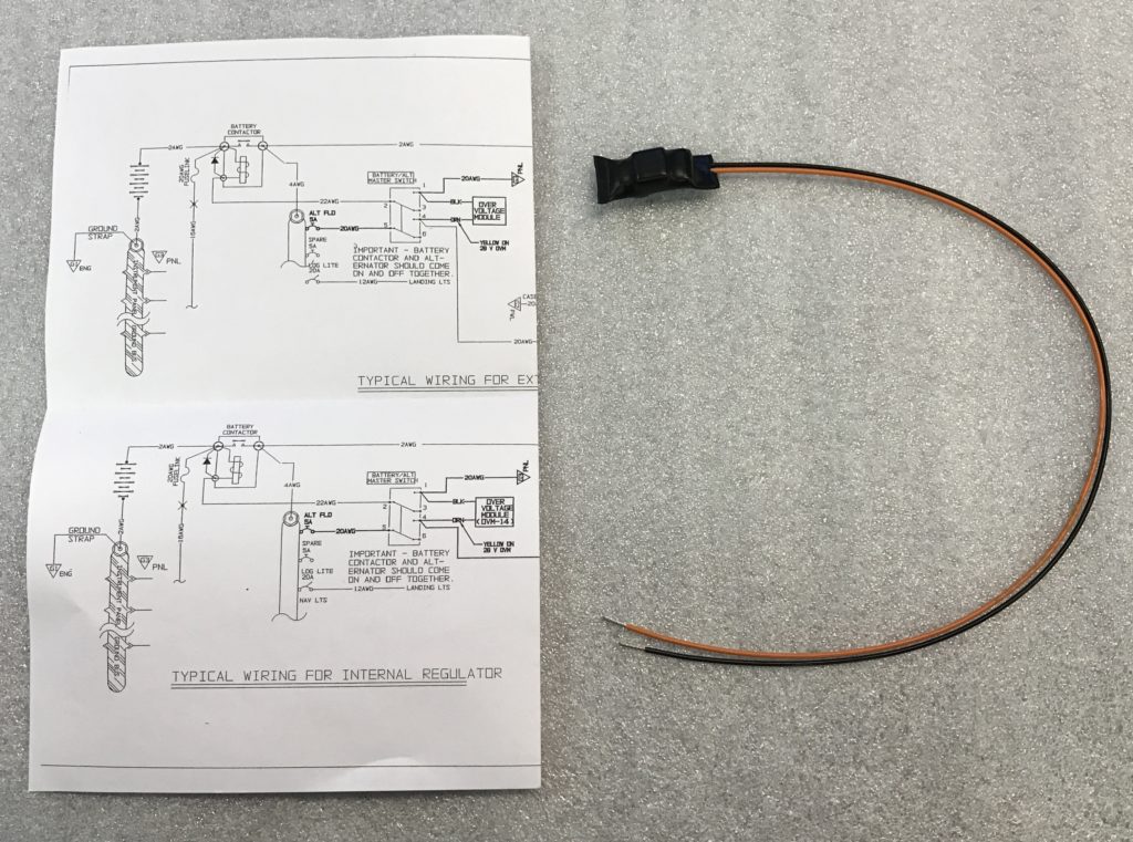
Seriously, PM me your email address, & I'll send you the OV protection diagram for an internally regulated alternator. If you want to talk about it, include your phone # & a time to call you.

Charlie
Slobovia Outernational (MS71)
 
Yes, AeroElectric.
Basically you wire relay contacts in series with the alternator B lead. The over-voltage protection unit will shut off the relay in case of high voltage.
 
SteinAir has what you want.

Call them to confirm with your application.

OVM14-a.jpg
 
Last edited:
OK, so I read through this entire thread regarding an over voltage situation that fried a guys avionics. After everyone went round and round about the situation, the thread never came to a sound conclusion before it was inexplicably closed.

The discussed solutions revolved around:
1. Keeping the lead acid battery.
2. Installing a Plane Power or B&C alternator with over voltage protection.
3. Installing a "crowbar" overvoltage protection in the system.

Thanks,
Chuck


When that thread came out I had just received delivery of an EarthX ETX900 I purchased to replace my failing Odyssey PC680. Even though I have a Plane Power alternator there were questions that were asked that were not answered. At least not to my satisfaction. I decided to eat the shipping cost and sent the unused EarthX back for a refund which I received.

I bought and installed a conventional Hawker SBS J16 Aircraft Battery which claims 220 CCA. It seems to turn my Skytec lightweight starter pretty robustly. With more information I might have stayed with the EarthX. Maybe next time.
 
Last edited:
No easy solution

This is one of those things in life without an "easy" solution.

As we all know, there is risk in everything we do and don't do.

An alternator can freak out and start sending energy out the B-lead.

If you have a good voltage regulator, it usually can stop this. There may be a case where it fails, and the energy continues down to the battery and the other stuff on the bus.

If the OV module is not fast enough, some can get to the electronics or the battery before the alternator can be stopped or the contactors de-energized.

Worst case seems to be smoked everything, including possibly p-mags.

I guess this is not quite as bad as a hard failure in the engine, but could be not far off.

Several things can be done to mitigate the risk:

1) high quality externally regulated alternator
2) big lead-acid battery to try to slow down the energy from getting to your electric stuff
3) good OV protection system

The cost-benefit of these items is not easily quantifiable, and if it has been done, I have not seen it. Besides, everyone's situation is different.

I had a perfect plan for an earthx on the FW. I'm re-thinking this, but have not yet made a decision.
 
SteinAir has what you want.

Call them to confirm with your application.

OVM14-a.jpg


"Making the image around 900 pixels wide or less preserves the proper word wrapping best on most monitors."

From the insert pictures guide.... top left corner of this page.
 
wide images

A few solutions to the wide image problem:

1) get a bigger monitor :D
2) get a plugin like "User CSS" for Chrome and add "#posts IMG {max-width: 100%;}" for vansairforce.com
3) convince DR to host images locally and activate some resizing options :D:D
4) teach 15,000 people to learn how to resize images :)
 
Last edited:
Image

The image is on SteinAir website. I use PhotoBucket for my images that I show (post) here and they get sized correctly for viewers by PhotoBucket. The image used from SteinAir was not too wide on their website display but the FORUM software made it much wider than what I was seeing.

I love my 4K 28" Samsung monitor on my Mac. Once you go large 4K Mac, you will not go back.
 
OK, so I read through this entire thread regarding an over voltage situation that fried a guys avionics.
<snip>
The discussed solutions revolved around:
1. Keeping the lead acid battery.
2. Installing a Plane Power or B&C alternator with over voltage protection.
3. Installing a "crowbar" overvoltage protection in the system.

<snip>

At this point, I know just enough to be dangerous about this topic and am hoping one of you could point me towards an easy, detailed solution to this potential problem.

Thanks,
Chuck

Chuck,

1. probably the easiest and lowest cost.
2. As you stated - costly but - with a B&C discount (free regulator) the PP and B&C will be close in cost. They do this a lot.
3. Actually two parts. A) You either need to modify the alternator for an external regulator so the B&C OVPM design can be properly installed, or B) get a OVPM designed for full amperage from the alternator and blow a full sized fuse.

Neither of #3 are over-the-counter solutions, although . . . . an alternator shop may be able to modify yours to an external regulator - there are parts made for this (just replacing the IR with a plug), but would have to match your alternator.
Then, use the B&C regulator (containing an OVPM) dial down the voltage to better match the EarthX.

All said we still don't know what happens if the voltage goes high, the EX kicks off, and suddenly the OVPM trips and the alternator field collapses. Although it is likely it is a safe scenario, it needs validation tested.

Short version (IMO): #1 is the easiest and most straight forward option.
#3 A -take your alternator to a shop (look under truck alternator/starter repair) and modify for the external regulator. Closest to off-the-shelf solution with all the fixings.

SteinAir has what you want.
Call them to confirm with your application.
Gary, instantly disconnecting the output under load might fry the alternator, but is cheaper than
panel parts. Good find.
 
Last edited:
You shouldn't be disconnecting the alternator unless it's already fried. Disconnecting the field stops the alternator *cold*
There's no need (and it's somewhat hazardous) to use a 'full size fuse' to protect the system from an OV event.


Aeroelectric. Aeroelectric. Aeroelectric.

Did I mention Aeroelectric?

Get the book. Soft copy is free. Read it.
 
So is the module that Stein Aero sells and the DIY plans from Charlie the same thing? If so, is the only downside to these that the cut the alternator off cold, which can damage the alternator? If so, why is that a big deal? The alternator already failed, and its cheaper than the avionics. What am I missing here? Why isn't the Stein Aero module a pretty cheap and easy fix?

BTW Charlie, what book are you referring too? I found the DIY Crowbar plans, but wasn't sure what book you are talking about.

Thanks.

The plans show a variable resistor for adjusting voltage trip point, but IIRC from Bob Nickel blogs, the production OVPM is the same as the diagram. Except for the adjustable part.

The OVPM diagram and the Stein part do the same thing, but it can be used to disconnect either the field supply (normal) or the alternator output, as in the Stein Diagram that Gary posted.

If your regulator fails high, and the OUTPUT is disconnected via fuse or solenoid (Stein diagram), then there will be voltage runaway and fry every component in the alternator, including the stator and possibly the rotor. It is high enough to break down the enamel wire insulation. It just won't get to the system.

If the OVPM only drops the FIELD, then all is good, no (further) damage to the alternator. Only replace the regulator.

http://www.aeroelectric.com - give them a call and get the book. Easier than printing at home.
 
Last edited:
I could be wrong

but in a way, an internally regulated alternator that has failed its regulator is already fried - in that the cost to replace it outright at Auto Zone is probably not significantly different from the cost to replace the IR innards if you somehow saved the windings from destruction. Certainly a small fraction of an AMU.

I'd have NO HESITATION about risking an IR alternator by opening a relay in the B-lead in order to save my avionics. Seems cheaper to implement than any other workable OVP scheme short of a purpose-made ER alternator and crowbar.

This is the way I see it too, but not sure if I'm missing something more important. An IR alternator is pretty cheap, so if it fails, my priorities are:
1. Not have a fire.
2. Protect my EMags so that my engine keeps running.
3. Protect my avionics and EMags from damage.

So, if the Stein module secures the alternator output from the rest of the system, but destroys itself, then as long as there's not a risk of fire, that would be OK.

But it sounds like the plans from Aeroelectric are a better solution because they "drop the field" which is better? For this method I will need to find someone to build it for me, because I am obviously not electrically inclined enough to do it myself.

Thanks for all of the input. I'm learning a lot here.
 
If your regulator fails high, and the OUTPUT is disconnected via fuse or solenoid (Stein diagram), then there will be voltage runaway and fry every component in the alternator, including the stator and possibly the rotor. It is high enough to break down the enamel wire insulation. It just won't get to the system.

Urban Legend, at least the rotor/stator parts.

Virtually any insulation is good for at least 600 volts. The failures would all be semiconductors, whose peak voltage tolerances might have been in the 50V range. And the 'load dump' failures from a couple of decades ago are unlikely to be a problem with current production (improved designs & components).

In any case, as Bill Boyd pointed out, most automotive alternators are so inexpensive that a full swap is no more expensive than buying (after finding) the regulator, and spending an hour of unskilled labor installing it.
 
Last edited:
The Aeroelectric Connection book is at:
http://www.aeroelectric.com/Book/AEC_R12A.pdf

Note that the pdf download will start as soon as you click the link. (Don't panic.)

edit: The download may not include the 'z diagrams', which are starting points for various wiring architectures. But the z diagrams are available elsewhere on the website.

You can also buy the book in print or CD form on the aeroelectric.com web site, and all subsequent updates are free (via pdf download).
http://www.aeroelectric.com/Catalog/pub/pub.html

Charlie
 
Last edited:
Urban Legend, at least the rotor/stator parts.

Virtually any insulation is good for at least 600 volts. The failures would all be semiconductors, whose peak voltage tolerances might have been in the 50V range.

Insulation to 600v - ok concede, but what is there real voltage and resulting thermal effect?

Just what does a lundell alternator produce for voltage with the field bootstrapped and at field magnetic saturation and maximum rpm? Anyone have data? 50 volts sounds low since charging voltage turn on is below engine low idle rpm.

Look at this:reference - - Ha - Aeroelectric, a favorite! Good reading for its comments on the effect of PbA battery effects on runaway voltage too.

A quote "If it?s so easy to get 110 VDC out of an alternator when you really want it, consider how easy it can be to get much more voltage even if you didn?t want to!"

And back to the question, just how high does it go?
 
This is the way I see it too, but not sure if I'm missing something more important. An IR alternator is pretty cheap, so if it fails, my priorities are:
1. Not have a fire.
2. Protect my EMags so that my engine keeps running.
3. Protect my avionics and EMags from damage.

So, if the Stein module secures the alternator output from the rest of the system, but destroys itself, then as long as there's not a risk of fire, that would be OK.

But it sounds like the plans from Aeroelectric are a better solution because they "drop the field" which is better? For this method I will need to find someone to build it for me, because I am obviously not electrically inclined enough to do it myself.

Thanks for all of the input. I'm learning a lot here.

There was some speculation that "dropping the field" voltage to an IR alternator won't necessarily shut it off if the regulator is toast and it's already on-line (been excited and is being driven by the engine). Different than an ER alternator where the field breaker gives positive in-flight control. The scheme Bob Nuckolls put forward and then withdrew for further study didn't pull the field excitation, but opened a contactor that took the B-lead off line, load-dump-style. That's the only way I would roll for now.

As far as I know, we've been waiting for better than five years for Bob to get his test stand running and get back to us with a plan.
Bill, do you have some reference for the details about this? I have the PP alternator, it is IR, and the only supply for the field voltage is the same as the voltage feedback reference to the regulator. So, the regulator can not get power from anywhere else if the field is off. Then, it won't work, period. Doesn't Uncle Bob also have a modification procedure for IR to remove the internal voltage supply/reference and move it to an external supply?
 
Why does the drawing say to have the battery contactor come on together with the alternator?

I am using a 2-10 switch so that I can activate the battery contactor first, then flip it on up to the alternator after engine start. (Externally regulated alternator) It will also allow me to cut off the alternator without cutting off the battery.

Is there a problem doing it as I have described?

Thanks
 
Last edited:
The better question is, 'Why does the split master exist?' (Learn its history.)
Another: Why don't cars have them?
Another: Why would you want to cut off the alternator without cutting off the battery? (Assuming you have proper OV protection, of course.)
 
Could you just try to answer my question?

I don't care what cars have and don't really want to study history re split masters.

I want the ability to continue battery use if the alternator fails via switching off the field only. I have OV protection.

Thanks
 
There is no operational problem with using a split master with an externally regulated alternator. But it does add additional mechanical/electrical failure point(s), and additional operational failure points (inadvertent operation of the alt half of the switch).
 
Read the 'connection!

It is available for free here http://www.aeroelectric.com/Book/AEC_R12A.pdf

I find it amazing that anyone can be a member of this forum, own an RV and not have read this book! It is, or should be, required reading on the order of the construction manual. It will tell you almost all you need to know other than info about the lithium battery.

I'll bet that just 20 minutes of reading the chapters on alternators and voltage regulation will lead you to modify your existing alternator for external regulation and ov protection. It is the lowest cost and wisest solution that you should probably do even if you keep the lead acid battery.
 
Ok, where is Dan H, time for a backyard alternator ramp up test? curious how fast the voltage would climb if the field voltage went to full field voltage, I remember as a kid backyard beater car testing if the alternator was good by doing this, I don't remember the voltage skyrocketing :rolleyes:
 
Ok, where is Dan H, time for a backyard alternator ramp up test? curious how fast the voltage would climb if the field voltage went to full field voltage, I remember as a kid backyard beater car testing if the alternator was good by doing this, I don't remember the voltage skyrocketing :rolleyes:

http://www.sto-p.com/pfp/pfp-transients.htm Try this bret.

I also tested alternators and generators before with the same method. It does not climb too fast with a honkin battery in the circuit and with engine idle speeds. Like 1-2-3 done, as I recall. It will go pretty fast with the battery load out of the circuit. Apparently the rotor inductance that causes the spike on pulling the field, also keeps the field from rising instantly.

All this sounds like a fun (and expensive, for auto zone) test, if I was already flying.


EDIT: Here is a good pdf worthy of downloading for personal archives. It explains the alternator and even uses a ND/PP style unit for the teardown. Very good reading for this thread.
 
Last edited:
Bill, do you have some reference for the details about this? I have the PP alternator, it is IR, and the only supply for the field voltage is the same as the voltage feedback reference to the regulator. So, the regulator can not get power from anywhere else if the field is off. Then, it won't work, period. Doesn't Uncle Bob also have a modification procedure for IR to remove the internal voltage supply/reference and move it to an external supply?

Don't know what Bob has to say, but I have modded alternators in sail boats to provide external regulation for better battery charging. In most cases, you need to pull one of the braids and route it externally to avoid self-excitation and bypass the internal VR. This seem pretty universal to provide external regulation on an internally regulated alternator. The problem is they are not universal in design regarding polarity. Some IR regulators work the positive side and some work the negative side. It varies by manufacturer.

Larry
 
Back
Top