What's new
Van's Air Force

Don't miss anything! Register now for full access to the definitive RV support community.

intake interferes with 4 into 1 exhaust

Bubblehead

Well Known Member
I am changing from the Vetterman 4 into 2 to a AWI 4 into 1 exhaust to solve a heat muff problem and hopefully pick up a little speed. I have run into an interference problem. The intake pipes on my IO-360 have a bend in them that interfere with the new exhaust system. Here are some pictures:

The old exhaust:


The new exhaust:


The intakes:


Has anyone else run into this? I've seen pictures of other 360s that have strighter runs between the sump and the cylinder. Does anyone know where I can get a set of those pipes and how hard is it to change over?

I'll call AWI this afternoon and get there opinion on it too.
 
Yeah, looks likes you have a IO-360C1C sump on your parallel valve. And those intake pipes you have are modified from stock. (note the welds)

You are looking at some major modifications to the intake or exhaust to make it work.
 
As they said, you have modified 200HP intake pipes. The intake pipes you want are shown here :
http://www.aeroinstock.com/products/Numerical-Part-Numbers/6162/0/product_cat/index.html
The ones listed for the 360 will make the intake pipes like an IO-360-M1B, which is what the exhaust was designed around.
Good Luck,
Mahlon
"The opinions and information provided in this and all of my posts are hopefully helpful to you. Please use the information provided responsibly and at your own risk."
 
IO-360-A1A vs IO-360-M1B intake tubes

As they said, you have modified 200HP intake pipes. The intake pipes you want are shown here :
http://www.aeroinstock.com/products/Numerical-Part-Numbers/6162/0/product_cat/index.html
The ones listed for the 360 will make the intake pipes like an IO-360-M1B, which is what the exhaust was designed around.
Good Luck,
Mahlon
snipped

Mahlon,
Are the angle valve IO-360-A1A intake tubes located and shaped the same as the parallel valve IO-360-M1B? I know that there is a slight difference in vertical length near the intake port.
Charlie Kuss
PS I found a drawing of the sump off of the link you provided, but none of the tubes. Perhaps I didn't look hard enough?
 
No, the IO360 200Hp pipes are shaped much differently then the IO-360-M1B pipes. The M1B pipes don't have the big curve down near the sump, they kinda go straight to the sump holes rather then curving down to them. The link I provided should take you to a parts page that tells you how much for each pipe and a p/n for each position. A picture of the pipes website can be seen here:
http://www.4sierratango.com/fwf4.htm
Good Luck,
Mahlon
"The opinions and information provided in this and all of my posts are hopefully helpful to you. Please use the information provided responsibly and at your own risk."
 
opps..bad link. That is a different sump and pipe set up. I will see if I can find some internet pics of the right one tomorrow.
Good Luck,
Mahlon
 
Either way, if you have a C1C sump like I think you do, the M1B pipes won't work because the sump sits farther back than the M1B sump does. Which means you'll need to modify the M1B pipes too. At least I think this is the case... Mahlon?
 
Lots of good information so far. I will check the still-attached data plate on the sump tomorrow when I go out to the hanger and report back tomorrow night. According to the paperwork I got with the airplane (I'm not the builder) the engine is a IO-360 A1F6D.

If I need to replace 4 intake pipes at about $300 each I will just go back to the Vetterman exhaust. Maybe Larry can tweak the set I have a little so I can get enough room for the cabin heat muff. As they are currently the crossover pipes are only about 1/4" apart so it's not possible to get a muff properly installed.

Please keep the info coming. I need to learn all I can.
 
That is good news for you, the IO-360-A series sump should work with M1B or equivalent intake tubes. Call Superior or ECI and see if you can get them cheaper.
 
I will call them this morning after I go to the hanger and get the sump info and the engine log books.

All the pictures of the engine can be found here: http://www.turboimagehost.com/album/2727/exhaust_system

I was able to bolt up the exhaust pipes from #1 and #4 but not #2 or #3. I think I want to change the intake pipes if for no other reason than to have the correct parts. Who knows, it may even give a little more power with shorter, straighter runs.
 
Either way, if you have a C1C sump like I think you do, the M1B pipes won't work because the sump sits farther back than the M1B sump does. Which means you'll need to modify the M1B pipes too. At least I think this is the case... Mahlon?
The C1C sump has the servo rear mounted, The A1A or A1B6 or A1/3B6D and M1B all use the same forward facing sump but the intake pipes are different for the parallel valve engine as compared to the angle valve engines. But the sump is the same.
Looked on the internet for pictures of the M1B pipes and I couldn't find any. The it dawned on me, DAAAAAAAH , why not look at our website.....
http://www.mattituck.com/images TMX/TMX Lft.JPG
and
http://www.mattituck.com/images TMX/TMX Rt.JPG
That is what the pipes look like.
Good Luck,
Mahlon
"The opinions and information provided in this and all of my posts are hopefully helpful to you. Please use the information provided responsibly and at your own risk."
 
Yeah, Lots of people modify a C1C sump to be front mount servo though. Either way, not the case with this one.
 
osxuser and mahlon_r,

I just want to verify that if I buy the intake pipes for a M1B or equivalent they should work with my C1C sump without modification? I compared the pictures from Mattituck with my pictures and it appears they are the same but even a 1/4" would make life difficult.

Is there any place other than Superior or ECI that I should check? Would secondhand be almost as good as new since these are not parts that wear?
 
Is there is a boss with a cover plate welded or bolted to it on the back of the sump? If there is, then it is a modified c1c sump and I am not sure if the pipes will work. But if there is no boss, on the rear of the sump, where a fuel injection servo could have mounted, then it is an A series sump, and the pipes I depicted should fit fine.
Other then used, I don't know of a less expensive source for the M1B pipes.
Good Luck,
Mahlon
"The opinions and information provided in this and all of my posts are hopefully helpful to you. Please use the information provided responsibly and at your own risk."
 
I'm at the airport now but at the FBO. I will go look at the back of the sump in a minute.

Here is the information from the plate on the sump:
IO-360-A1B6
Eng No. 1-23565-51A
200 hp at 2700 rpm

Strange that it would say 200 hp. The engine is a parallel valve 180 hp IO. Perhaps the sump came from a 200 hp engine.

The original log book for the engine says it was from a C-177 and the engine is a O-360-A1F6D.

I'll be back in a minute with the info on the back of the sump.

UPDATE - there is no plate on the back of the sump. My guess, given the data plate info still on the sump, is that I have a 200 hp sump on a 180 hp engine, in which case it might be difficult to get straight intake pipes to fit properly. Perhaps I should bite the bullet and put the right sump and tubes on? Perhaps an after-market one that would improve air flow. Any ideas or thoughts or opinioins?

I took some more pictures of the front and back of the sump and will post them when I get home tonight.
 
Last edited:
Here are pictures of the front and rear of the sump. There is no plate on the back of the sump, so I guess this is not a C1C sump. The data plate may be correct and it is a A1B6 sump.


Yes, I need to clean up the oil a little, although it shows up in the picture a lot more than when you see it live.

I think I will try to find the right sump and intake pipes or an aftermarket sump and pipes.
 
Part Number comparison

Here are pictures of the front and rear of the sump. There is no plate on the back of the sump, so I guess this is not a C1C sump. The data plate may be correct and it is a A1B6 sump.

snipped
Yes, I need to clean up the oil a little, although it shows up in the picture a lot more than when you see it live.

I think I will try to find the right sump and intake pipes or an aftermarket sump and pipes.

Yes, that's a 200 HP forward facing sump (IO-360-A1B6) installed on your parallel valve 360. I suspect that the tubes were cut and welded to compensate for a 3/16" vertical height difference between the parallel valve and angle valve engines relating to distance from the tube's mounting at the sump and the intake mounting flange on the cylinder head.

I referenced Parts Catalogs PC-306-14 (IO-360-M1A) for parallel valve engine with forward facing fuel injector servo and "angle valve" style intake tubes.

Sump part number is LW-13864
Intake tube cyl #1 42E22611
#2 42E22612
#3 42E22613
#4 42E22614

Referencing Parts Catalog PC-406-1C (IO-360-Axxx & Bxxx) parallel & angle valve engines, for the IO-360-A1B6 the part numbers are:

Sump 74384
Intake tube cyl #1 78741
#2 78742
#3 78743
#4 78744

The part numbers differ, so obviously the parts differ in some manner or perhaps have been superceded. FYI The sump and intake part numbers shown for the IO-360-A1B6 also fit the following models.
IO-360-A1A
IO-360-A1B
IO-360-A1B6D
IO-360-A1C
IO-360-A1D
IO-360-A1D6
IO-360-A2A
IO-360-A2B
IO-360-A3B6D

I hope this helps. Perhaps a manufacturer makes a 4 into 1 system for the engines listed above?

Charlie Kuss
 
Charlie,

That's a lot of great information. I'm going to look into replacing the sump and pipes for the proper ones for my parallel valve engine. Perhaps I will be able to find a second hand set for a reasonable price.

I've also ordered the Lycoming overhaul manual for the 360s. Perhaps I should order the parts catalog you list in your posting.

Thank you for doing the great research. It is very helpful.

John
 
Yep, the -A model sump which you have (especially if it's out of a Cardinal RG) should match with the M1B intake tubes on a Parallel valve engine.

Confused yet? :D

The problem is there are different designations for O-360's and IO-360's.

O-360-A and IO-360-B are both updraft parallel valve (the IO is injected...)

IO-360-A series are Fwd Facing Angle Valve

IO-360-C series are Rear Facing Angle Valve (But can be modified for FWD facing, which many people do)

IO-360-M series are Parallel Valve FWD facing...

Clear as mud.
 
I am confused, but I am getting more comfortable every day with that feeling!

This is good news though. It means that I don't have to replace the sump, I just have to find some reasonably priced M1B tubes!
 
Superior sump or just new intake pipes

OK, things are starting to come together now. It seems I can put a Superior Air Parts sump and tubes on for about $1850 or just get the tubes from Aerosport Power for about $600. Either way it's a lot of money.

Pictures of the sump can be seen at their website:
http://www.superior-air-parts.com/pieceParts_Sumps.asp

The Superior sump is really beautiful, but does it help performance over the normal Lyc sump? If so, is it worth the extra money?

BTW, how difficult is it to change intake tubes? The cylinder end looks like it is just a bolt up retainer and a flange on the pipe. How is the sump end connected on a normal Lyc sump? Snap rings?
 
Last edited:
Bobby's Planes n Parts
in Texas
940 682 4220


the tubes are swedged or rolled into the sump housing

cary
 
I don't believe the Superior tubes will fit the M1B sump. The Superior tubes only go with the Superior sump, as far as I know. I don't think you will see a noticeable difference in power between the Superior sump and the M1B sump. The tubes slide into the sump on the M1B and are held in place by the attachment to the cylinder head. On the vertical style Lycoming sumps, the tubes are attached at the cylinder head in the same fashion as with the M1B but the sump end is attached to the sump with a hose and clamps rater then sliding into a hole.
Good Luck,
Mahlon
?The opinions and information provided in this and all of my posts are hopefully helpful to you. Please use the information provided responsibly and at your own risk."
 
Bobby's Planes n Parts
in Texas
940 682 4220


the tubes are swedged or rolled into the sump housing

cary

I bought a Lyc rebuild manual - wish I'd bought the parts manual too - and read the portion about intake tubes. If I understand correctly, to install new pipes with this manifold I will need a swedging tool to swedge the pipe to the sump. I don't have such a tool but I'm sure someone in my area does.

Does the sump have to be off the engine to swedge the pipe on? The overhaul manual seems to say that because you know when you've swedged enough because there is greater resistence to the swedging tool.

mahlon_r - if I understand your comment correctly perhaps the pipes are swedged while off the engine then slipped into place.

If I am going to remove the sump anyway perhaps I'll put a new sump and pipes with the hose and clamps and avoid the swedging operation. I've ordered a set of regular tubes from Aerosport Power so I guess I will learn some things when I see them.
 
Bub

A repair shop at our local ariport has a rolling tool that I have borrowed/bartered in the past.

But , then he has every tool/gadget known to man.

I would assume that its not that uncommon for a good power plant shop to have one.

cary
 
oh as a PS


the sump needs to be accessible.

Like separate from the engine and on a table.
 
Thanks for the info, caryr. I'm sure the local A&Ps have the right tools. This has turned into a big can of worms. All I wanted to do was get a heat muff on the exhaust, and now I'm looking at removing the sump!

Maybe I should call Larry Vetterman again and see if he can tweak the current exhaust system to give me enough room for the muff! Grrrrr!

It's the classic "You can't get there from here - you have to go somewhere else first!"
 
I think you are confused. The intake pipe roller tool is needed for vertical sumps not for the horizontal type sump you have. The sump/intake manifold you have doesn't require any tools to install the tubes. The tubes just have an o-ring that goes around the tube itself and then that tube and o-ring slides into a cavity in the manifold. Nothing holds it there, but the attachment of the other end to the cylinder head. So if you were to replace a intake tube that you have, all you would do is unbolt it from the cylinder head and slide it out of the intake manifold. Slide the new one with a new o-ring into the cavity the old one came out of, and then bolt up the other end to the cylinder head with a new gasket. Only tools required are a 7/16 socket, an extension and a ratchet wrench to turn them with.
Good Luck,
Mahlon
"The opinions and information provided in this and all of my posts are hopefully helpful to you. Please use the information provided responsibly and at your own risk."
 
thanks mahlon

it takes a few smart people like u to keep us on the straight and narrow around here.
 
A heat muff shouldn't be an integral part.

How about just building a new one.

Nothnig says it has to be a particular shape.
 
Or you can see if they can upgrade the crossover to the muffled one, that has copious amounts of heat.
 
mahlon_r - thanks for the amplification. I have ordered the new intake pipes and will try that when they get here. Unfortunately they did not make it in time to install before this weekend so I think I'm going to put everything back together this morning so I can fly over the holiday weekend. Maybe even take an overnight trip somewhere pretty.

cary_r - the muff is not integral nor is it the problem. The problem is on the set of Vetterman pipes I have the crossover where the muff goes is too close to the other exhaust pipe so the muff is pressing on the other pipe and burns through. There is not even room for exhaust pipe wrap between the heat muff and the other exhaust pipe. I've tried relocating the muff but the only other place with physical room for the muff is where there is a slip joint, so I would risk getting carbon monoxide in the cabin.

Current plan - try the new intake pipes.
Backup plan - ask Larry Vetterman to tweak the current pipes to make room for the muff.

This forum topic has been very enlightening and helpful. Just another example of the huge value this forum and it's members provide! Thanks to one and all, and especially Doug. It's a great community!
 
Update - new intake pipes

I ordered a set of new intake pipes correct for my engine from Aerosport Power to eliminate interference with the new AWI exhaust system. Here are some pictures of the pipe and o-rings. The middle picture is a little fuzzy but shows the groove for the o-ring.


I will be installing them Saturday morning. Is there anything I need to be careful of other than making sure the o-rings don't get cut and lubricating the bolts with anti-seize? Do I lubricate the o-rings before installation? If so, with what?

I'll let everyone know if they fit up right and if there were any other problems.
 
I will be installing them today (Sunday). Is there anything I need to be careful of other than making sure the o-rings don't get cut and lubricating the bolts with anti-seize? Do I lubricate the o-rings before installation? If so, with what?

Just bumping this up - heading to the hanger in an hour or so to install the tubes and could use some advice on lubricating the O-rings.

Thanks
 
All better!

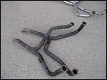
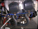
Last week I finally got the new exhaust system in, after getting the new intake pipes in, after changing... Well, you guys know the drill. I test flew it Wednesday night for 20 minutes and everything seemed good. Came back to the hanger, felt around the cowl and found some pretty warm or almost hot spots, then removed the cowl to inspect everything.

The new intake and exhaust both were fine. I knew some delamination of the lower cowling had taken place through the years, and it was a little worse after this flight so I took it home for repair. I cut away the damaged interior skin, feathered the good skin out, and laid up some BID using West Systems epoxy with the slow cure hardner (206?). Used some peel ply to soak up any excess resin. The next afternoon I pulled the peel ply up, sanded the surface a little, and everything looked great.

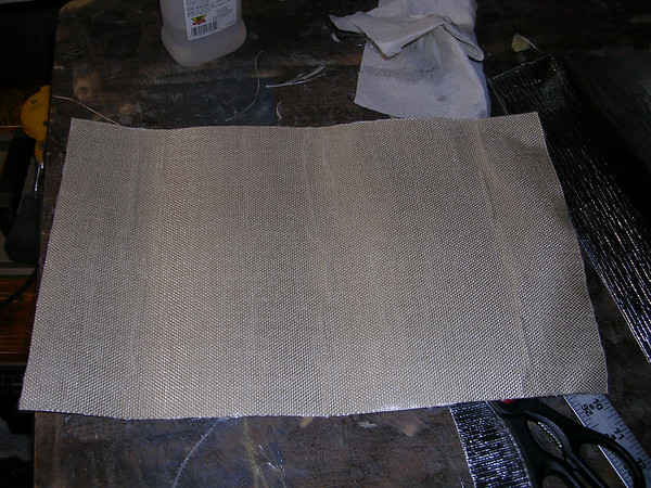
I was concerned about heat damage to the new fiberglass so stopped at a hot rod shop Thursday and bought some heat barrier. I'll get the name and stock number and add it to the posting later. It is basically a thin layer of insulation with a shiny side and a sticky side. I cut it to fit the cooling air outlet ramp, and stuck it in place.

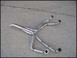
Saturday morning I went to Oshkosh (by car) but Sunday checked all the nuts and bolts on intake and exhaust, then put the cowling back on and went flying. Took performance numbers at 8500 feet and 7500 feet. I need to convert to density altitude but it looks like I picked up a few knots with the AWI 4 into 1 exhaust. I also tried the cabin heat, and got a huge blast of very hot air when I opened the air box. That should make flying this winter or at higher altitudes a whole lot more comfortable.

I flew for about an hour, landed, taxied in and then checked the cowl temperature by hand after shutting down. The area where I had put the insulation was barely warm, while areas to either side were hot but not uncomfortably hot. I will probably buy another 12 x 24" piece of the stuff and add a little more inside the lower cowl where the individual pipes come down from the cylinders. I also reached up inside the cowling after everything was cool. The reflective insulation was still stuck down tightly into place, and as far as I could feel the repaired areas withstood the heat and vibration of the flight.

All in all this was a good project that unfortunately took up 1 month of the flying season, but I now have a real cool looking exhaust and great cabin heat, which was the original reason to do this modification.

I'll post pictures tonight along with the name of the insulation material.
 
The brand name of the material I used is "ThermoTec" and the product is called "Aluminized Heat Barrier - Adhesive Backed." The package I bought contained a 12" x 24" piece of the barrier and is part #13575.

It cuts easily with a scissors, and the adhesive was very sticky. The barrier has stayed put for two flights so far. It seems to be down tight and should stay in place for a long time. I'm going to add a narrow strip of it to each side of the lower cowl to block some heat from the two pipes closes to the cowl.

The package does not show the price, but I think I paid about $20 for it. I'll post pictures later.
 
Wonder how that product compares to Vans product Cowl Heat Protector ($5.30 for 12" by 30"). The description of the two products sound similar but Vans product doesn't really have an insulation layer that I could discern, appeared to be just heavy aluminum foil with a sticky backing.
 
Aluminized Heat Barrier by ThermoTec

Here's a link to the ThermoTec website http://www.thermotec.com/

Here's what their website page http://www.thermotec.com/aluminized-heat-barrier.html says about this material:

"The Aluminized Heat Barrier is made up of woven silica with a flexible aluminized finish. The highly-reflective surface of the material is capable of withstanding radiant temperatures in excess of 2000?F."

The silica mat must provide some good barrier to the heat because the areas where I put it are considerably cooler than the areas where I didn't.

Here's what it looks like and where I applied it:

Woven Silica and Adhesive Side Up
348742576_n7msY-M.jpg


Aluminized Side Up
348742355_RDjHa-M.jpg


Pictures of the cowl repair and the material can be seen here: http://tangodelta.smugmug.com/gallery/5664926_GpvQU/1/348742355_RDjHa
 
Just some final updated information

I checked with Aerosport Power (thanks Sue) to get the part numbers of the tubes I bought and installed in July 2008. Here they are:

APS42E22611
APS42E22612
APS42E22613
APS42E22614

They have worked fine for about 100 flying hours.

Charlie Kuss and I conversed via email and I think I can say what engine I have.

It's an 180 hp O-360 A1F6D with a sump from a IO-360-A1B6. This gave it horizontal induction. The fuel injection system is a RSA-5EX which according to Don Rivera "is a RSA-5 fuel servo that has been rebuilt for experimental use. All parts are standard RSA-5 parts. It is calibrated to P/L 2524450 flow sheet."

So to my mind I have a IO-360 A1F6D even though Lycoming never made such an animal! It runs good though!
 
More accurate model description

I checked with Aerosport Power (thanks Sue) to get the part numbers of the tubes I bought and installed in July 2008. Here they are:

APS42E22611
APS42E22612
APS42E22613
APS42E22614

They have worked fine for about 100 flying hours.

Charlie Kuss and I conversed via email and I think I can say what engine I have.

It's an 180 hp O-360 A1F6D with a sump from a IO-360-A1B6. This gave it horizontal induction. The fuel injection system is a RSA-5EX which according to Don Rivera "is a RSA-5 fuel servo that has been rebuilt for experimental use. All parts are standard RSA-5 parts. It is calibrated to P/L 2524450 flow sheet."

So to my mind I have a IO-360 A1F6D even though Lycoming never made such an animal! It runs good though!

John,
The part numbers for your intake tubes are for the IO-360-M1A engine. I suspect that these same intake tubes are used on the IO-360-M1B engine. However, I can not verify that, as I don't have a parts catalog for the -M1B. Can someone with a -M1B parts catalog verify or dispute my suspicion.
A more accurate description of your engine would be an IO-360-M1B6, if you ditched the dual magneto. With the dual magneto, I would call it an IO-360-M1B6D. You basically made an IO-360-M1B with a counter weighted crankshaft [hence the 6 as the 4th digit of the suffix] This designation would more accurately describe your intake and fuel system. Your engine would differ from a true IO-360-M1B only in the crankshaft, accessory cover, it's related items (if you didn't switch it out for a dual magneto item) and the models of magneto(s) used.
Charlie Kuss
 
I still have the dual magneto setup. I don't like it but don't have much choice at this point. I definitely have the crank counterweight assemblies as shown in the Lyc parts manual.

The only problem with calling it an IO-360-M1B6D is according to the M1B parts manual they don't show any crank counterweights. Perhaps the M1A manual shows them. It's probably more accurate to stick with the IO-360-A1F6D

I would love to get away from the dual mag setup. I don't like the single point of failure and I would like to go to a more modern ignition system. It's not important enough to me at this stage to open the can of worms (and my checking account) and changing the whole accessory case of the engine. If I ever do a major O/H I might tackle it or buy a core and put my cylinders, starter, alternator, prop gov etc. on it.
 
John,
Can someone with a -M1B parts catalog verify or dispute my suspicion.
From the M1B Parts book:
42E22611
42E22612
42E22613
42E22614
Good Luck,
Mahlon
?The opinions and information provided in this and all of my posts are hopefully helpful to you. Please use the information provided responsibly and at your own risk."
 
Possibly more than one way to skin that cat

I still have the dual magneto setup. I don't like it but don't have much choice at this point. I definitely have the crank counterweight assemblies as shown in the Lyc parts manual.

The only problem with calling it an IO-360-M1B6D is according to the M1B parts manual they don't show any crank counterweights. Perhaps the M1A manual shows them. It's probably more accurate to stick with the IO-360-A1F6D

I would love to get away from the dual mag setup. I don't like the single point of failure and I would like to go to a more modern ignition system. It's not important enough to me at this stage to open the can of worms (and my checking account) and changing the whole accessory case of the engine. If I ever do a major O/H I might tackle it or buy a core and put my cylinders, starter, alternator, prop gov etc. on it.

John,
You have one, or possibly two choices. Install a single magneto in place of the dual magneto unit and install an electronic ignition, using a crankshaft [up by the flywheel] trigger sensor.
Check with Mahlon or another expert on the validity swapping your accessory cover and related parts with those used on a dual magneto unit. The accessory gear spindles may or may not differ. I don't know, as I haven't dealt with any of the dual magneto engines.
Charlie
 
John,
Check with Mahlon or another expert on the validity swapping your accessory cover and related parts with those used on a dual magneto unit. The accessory gear spindles may or may not differ.
Different crankcase, gear train gears and crankshaft...not a practical conversion as far as I am concerned.
Good Luck,
Mahlon
?The opinions and information provided in this and all of my posts are hopefully helpful to you. Please use the information provided responsibly and at your own risk."
 
Offset Heater Muff

If your issue is clearance for a heater muff, suggest you check out Larry Vetterman's unit. I just received a x-over system from him for my RV6 (absolutely beautiful by the way:))The pieces which form the end plates are fabricated with an offset that shifts the c/l for the muff 3/8" relative to the pipe c/l so it should fit in the 1/4 inch envelope you are dealing with. With the end-plates properly oriented for clearance, install the muff with with inlet & outlets oriented as needed and secure using the worm-drive clamps Larry provides in his kit. Can't put the muff on the straight sections huh?

Mahlon - If you are reading this, hope my engine is on schedule for Nov. delivery as the stuff I will attach is arriving!
 
Old thread I know, but if I had a 200hp C1C, could I just add a new cold air induction set up as a fix to the rear sump issue?
 
Back
Top