az_gila
Well Known Member
VAFers,
I'm planning on an Aerosport panel with two 10 inch Skyview HDX units.
With the large units and the Aerosport panel restraints it seems like the only location available for the three small Dynon panels is above the main units.
This would be for the knob, autopilot and comm panels.
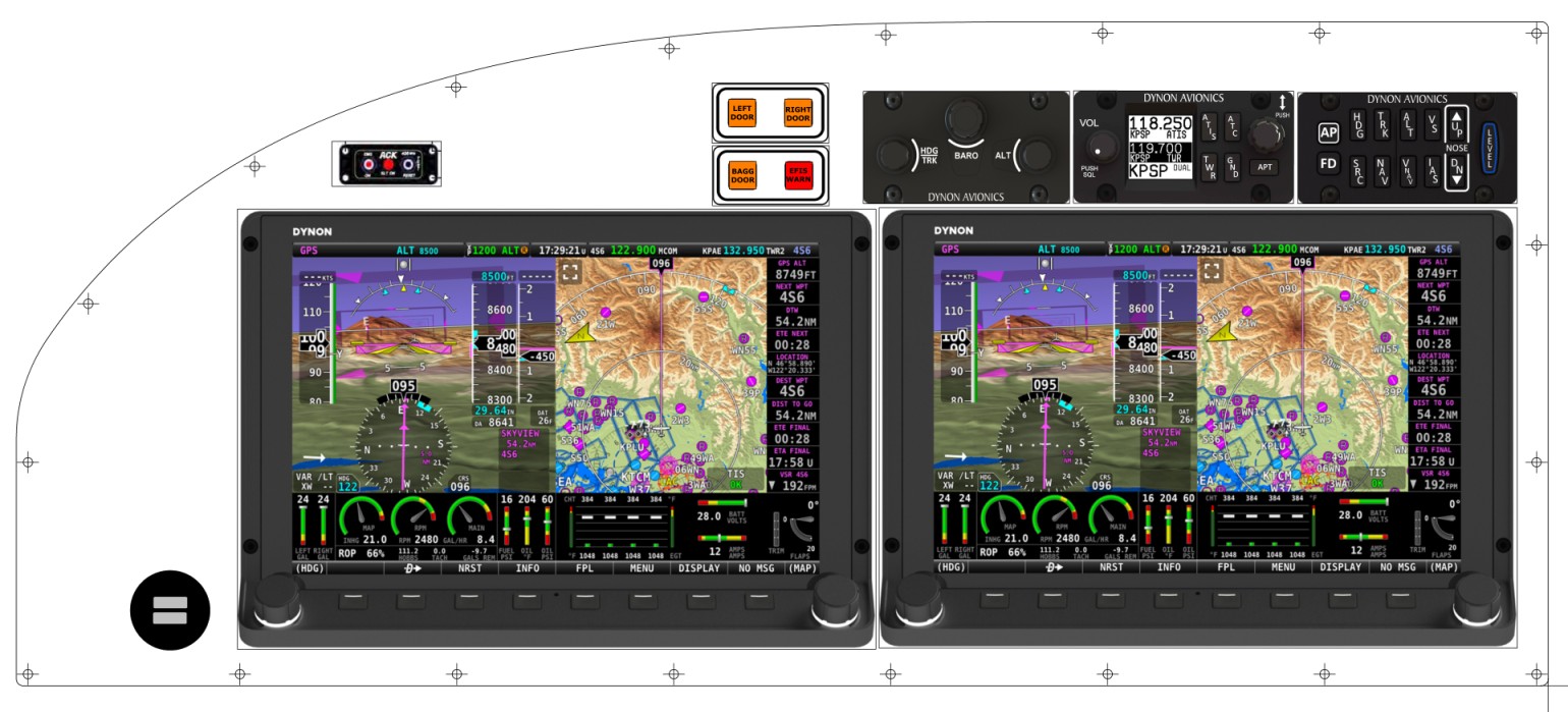
Does anyone have a similar panel in currently?
Are there any access/reach issues getting at the three small panels that high on the panel?
Any other comments?
I'm planning on an Aerosport panel with two 10 inch Skyview HDX units.
With the large units and the Aerosport panel restraints it seems like the only location available for the three small Dynon panels is above the main units.
This would be for the knob, autopilot and comm panels.
Does anyone have a similar panel in currently?
Are there any access/reach issues getting at the three small panels that high on the panel?
Any other comments?
")