PilotjohnS
Well Known Member
Just thinking about how I can use the G3x / GEA 24 to measure brake caliper temperatures.
I have an extra roll of thermocouple wire, and there are two spare inputs to the GEA 24 since I am only using 4 cylinders. Several things come to mind:
1) Do I run the thermocouple wire from the brake caliber all the way to the panel? This runs the risk of picking up interference from the comm antennas and such on the bottom of the airplane. Maybe I run twisted shielded pair to the wheel fairing and a short section of thermo wire to the caliper; this will cause some inaccuracy, but minimize the noise intrusion into the microvolt signal.
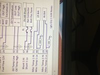
2) can the G3x cylinder input be renamed or is there a brake temp input I could tap into?
3)if i use cylinder 5 and 6 inputs, can the yellow and red caution warning temperatures be assigned a different value then the other cylinders? Do I need to reassign the temp limits since the max brake caliper temp is really close to the cylinder temp anyway?
EDIT: i think I will use the extra two temp inputs and not the cylinders 5&6.
So this is a go, I am going to do this. My next step is to measure the inaccuracies using twisted shielded wire verses all thermo wire. Time to Break out the lab equipment.
Just some things to think about before I close up my fuselage wiring.
I have an extra roll of thermocouple wire, and there are two spare inputs to the GEA 24 since I am only using 4 cylinders. Several things come to mind:
1) Do I run the thermocouple wire from the brake caliber all the way to the panel? This runs the risk of picking up interference from the comm antennas and such on the bottom of the airplane. Maybe I run twisted shielded pair to the wheel fairing and a short section of thermo wire to the caliper; this will cause some inaccuracy, but minimize the noise intrusion into the microvolt signal.
2) can the G3x cylinder input be renamed or is there a brake temp input I could tap into?
3)if i use cylinder 5 and 6 inputs, can the yellow and red caution warning temperatures be assigned a different value then the other cylinders? Do I need to reassign the temp limits since the max brake caliper temp is really close to the cylinder temp anyway?
EDIT: i think I will use the extra two temp inputs and not the cylinders 5&6.
So this is a go, I am going to do this. My next step is to measure the inaccuracies using twisted shielded wire verses all thermo wire. Time to Break out the lab equipment.
Just some things to think about before I close up my fuselage wiring.
Last edited: