Agree, the inflated fuel flow doesn't make much difference if I remember to turn the boost pump off after initial climb. It's an accurate system otherwise. Still, I've been thinking about the cause a fair bit just because it's fun. Planned to test the following before discussion, but there's no telling when I might get to it. So, what the heck...assume a FF sender between a rotary pump and the engine-driven pump, and try this one for size.
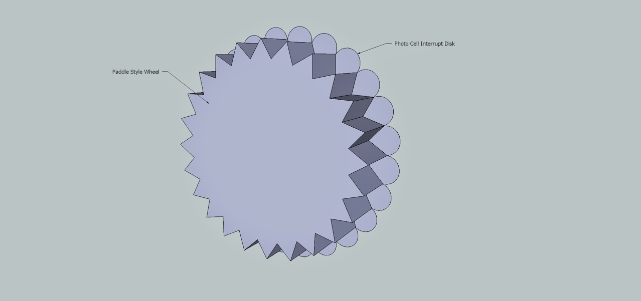
There are only two ways the transducer can output more counts. Either fuel flow must actually increase (rotor turns faster, more counts in a given period of time), or the rotor must stop and physically reverse momentarily. Pressure oscillations alone won’t do it. There must be actual reverse flow. Doesn’t take much if the rotor has a lot of shutters. For example, if the rotor has 36 shutters, it would only need to reverse 10 degrees of rotation to add a count.
So, assuming no downstream accumulator, what are the possible sources of reverse flow?
Take a good look at engine-driven pump operation. The accessory case idler gear eccentric moves the pushrod, which pushes the pump lever, which raises the diaphragm, compressing the main pump spring, and moving fuel into the pump chamber through the inlet check valve. As the eccentric nears TDC, the diaphragm motion slows, then stops, as does inlet flow. The inlet check valve is spring loaded (elastomeric or metal spring), so it closes in sync with the motion of the diaphragm. As the eccentric moves beyond TDC, the lever no longer holds the diaphragm in the raised position, and it starts downward, driven by the compressed pump spring. Pump output pressure is a function of spring force. The outlet check valve opens and fuel flows out of the pump chamber.
Note that spring force is not constant. The fully compressed spring pushes the diaphragm harder initially, as compared to later, near the end of its travel. The “fuel pressure” we see on our panel instrument is an average. Since the far end of the line is open to the servo, actual fuel pressure in the line dropped while the pump was busy with an intake stroke. The initial rush of fuel into the line raises pressure to equal spring force divided by diaphragm area. Line pressure decreases moderately as the spring becomes progressively more relaxed, then drops more quickly as the pump enters another intake cycle.
Now consider what happens when you turn on the boost pump.
The lever raises the diaphragm, but inlet fuel flow does not slow or stop as the eccentric nears TDC. Instead, flow continues through TDC, as the boost pump pushes fuel through the inlet check valve, across the pump chamber, and out the exit check valve. Servo line pressure did not drop during the intake stroke, and as the pump lever releases the pump spring, initial flow is out through both open check valves....the source of reverse flow.
The diaphragm only moves until (spring force/diaphragm) = boost pump pressure. If that happens quickly (weak spring, strong boost pump, i.e. a system in which boost pump pressure is high compared to engine pump pressure), the inlet check valve never fully closes. If the spring is strong and the boost pump is weak (relatively speaking) the check valve would close, but only after a reverse flow pulse while the check valve was in transit.
How to prove or disprove it? The engine driven pump would generate a reverse flow at (RPM/2)/60 = hertz. The rotary electric boost pump used with fuel injection is unlikely to generate a reverse flow, but if it did, it would be at a much higher rate, and it would not vary with engine RPM. So, hook a scope to the transducer output. If the the signal shows regularly spaced clusters of rotor counts (extra counts in a short time period, indicating reverse flow), and the interval at which clusters appear correlates with engine RPM, the engine pump is the source.
So who has a scope program on a laptop?


")