What's new
Van's Air Force

Don't miss anything! Register now for full access to the definitive RV support community.

Oil Cooler Shroud

wirejock

Well Known Member
Anti Splat makes some awesome products but I wasn't crazy about the size of the oil cooler shroud. Time to fabricate. I will post progress.
Start with a 3-7/8" plug. Final shroud should be pretty close to 4" after layup.
Cut another block the size of the shutter.
Glue the plug to the block.
Clamp it in the vise and use a piece of emery cloth to shape the cone. Just like polishing shoes. Takes about 10 minutes.
Coat with neat epoxy then micro.
Cure.
Final shroud will have a flat 1/2" flange all the way around for mounting.

Next steps...
Another coat of micro.
Final sand
Release agent
Layup
Easy Peasy. Thanks to Dan for all his tips.
20210302_115209.jpg
20210302_132214.jpg
20210302_145650.jpg
 
Nice work Larry.

I did something similar. However, the "ring" that the SCEET was clamped to just didn't hold up. I ended up bonding in a section of aluminum duct.

Pictures attached.
 

Attachments

  • IMG_1805.jpg
    IMG_1805.jpg
    462.2 KB · Views: 329
  • IMG_1806.jpg
    IMG_1806.jpg
    336.3 KB · Views: 349
  • IMG_1807.jpg
    IMG_1807.jpg
    504.9 KB · Views: 325
Oil cooler duct

Don Broussard
RV9 Rebuild in Progress
57 Pacer
 

Attachments

  • 2150A45D-19E4-4C56-9EE6-6AC0E180F54B.jpg
    2150A45D-19E4-4C56-9EE6-6AC0E180F54B.jpg
    290.9 KB · Views: 422
  • E3CCF162-DA41-4DD5-96D0-55E3F65E654F.jpg
    E3CCF162-DA41-4DD5-96D0-55E3F65E654F.jpg
    487.9 KB · Views: 393
Duct

Now I'm wondering if I should have shaped in some direction. Oh bother. Good practice.
 
You would like to keep the diffusion angles shallow and the shape smooth. Brian Decker's is a very good shape.

The Anti-splat is much too abrupt a diffuser with sharp corners and big angle change. Will result in a 4" diameter jet flow and back eddies.
 
Last edited:
Terms

You would like to keep the diffusion angles shallow and the shape smooth. Brian Decker's is a very good shape.

The Anti-splat is much to abrupt a diffuser with sharp corners and big angle change. Will result in a 4" diameter jet flow and back eddies.

Please explain. How should the air flow from the hole in #4 baffle be metered and directed to the oil cooler?
I haven't assembled the baffles yet so now is the time to build it right. Using the bigger RV10 oil cooler in my IO360M1B will no doubt require some metering during colder flights. I was going to use a blast gate but it was way too heavy.

Vans sells the same oil cooler shutter for this exact use
https://shop.vansaircraft.com/cgi-b...302-244-33&browse=engines&product=oil_shutter

Is there a better valve available?
Maybe this.
https://www.ecomfort.com/Fantech-IR...0RZcoJCt3rMzLeHWDdDj_RwlWUv0syN4aAhPsEALw_wcB

I could probably make something like this work.
https://www.amazon.com/dp/B00AA2WGF...imm_PSBH79X9V4AJEQ33MR9V?_encoding=UTF8&psc=1

Here's the RV10 plan. No shutter on the big six cylinder.
20210303_213605.jpg
 
Last edited:
Larry,

My concern for the shutters is that when 'wide open' they still present a fairly significant obstruction to the flow into the cooler. For the parallel-valve 360 engines this seems to be fine - they are really easy to cool the oil. For angle valve engines, (or any engine with piston oil squirters) there is a lot of heat load in the oil, and when it is warm out, you are going to want full cooling.

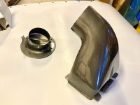
So, I favor a butterfly valve/throttle valve type control, right at the flange where the 4" tubing attaches to the back of the cooling baffle. I made my own, but I think you can buy them in a section of 4" aluminum tubing that you can insert in the middle of the 4" tubing run, or you could cut one side close to the valve bushings and have a flange welded onto it to attach to the cooling baffle. Take a look at the one that Don Broussard posted in post #5.

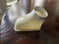
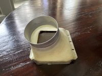
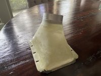
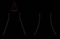
Where you make the transition from the 4" round tubing to the face of the oil cooler, you are slowing the flow down and you want the flow evenly distributed over the face of the cooler. If that transition is too abrupt, or has sharp corners, you basically get a 4" diameter jet of flow impinging on the face of the cooler, and then recirculating around in there. Now....it is not really that big a deal, since the flow velocity is fairly slow in the 4" tube, so the pressure loss is not very big even with an abrupt transition. But you would like to do the best you can. If you are going to make a custom fiberglass adapter, shape it well. As I said, Brian Decker's, pictured in post #4 is very good. Note that it takes some length to make a good transition, and that often dictates angling off in some direction. That is OK. The idea is to get the flow velocity low as it approaches the cooler. And if the velocity is low, it doesn't matter much what direction it is going. It will get slurped into the cooler by the large pressure differential.

The one redeeming aspect of the firewall cooler mount/adapter for the RV-10 is that it takes in air perpendicular to the cooler face, and forces it to distribute evenly over the face of the cooler by virtue of the triangular shape which reduces area as the flow progresses along the face of the cooler. As long as the incoming velocity is low, this is not too bad. But not as good as a smooth diffuser-type transition.

I have just one quick and poor quality pressure measurement on my old arrangement which had 3.5" scat tubing rather than 4", and the adapter for the cooler was very similar to what Van sells for the RV-10 firewall mount, so pretty abrupt. With the 3.5" scat tube, the velocity coming into the adapter/mount is fairly fast. In that one measurement, the upper cowl plenum pressure was about 10" of water, the lower cowl pressure (and the oil cooler outlet pressure) was about 1.4" of water, and the pressure at the oil cooler inlet was about 5.5" of water. In other words, I had lost half of the available pressure to drive flow thru the cooler in the 3.5" duct and abrupt transition to the cooler. I don't have measurements on my new system yet which has a 4" smooth tube duct and a transition that looks very much like the one Brian Decker made.
 
Last edited:
Larry, here's a graphical presentation borrowed from a textbook:

https://www.danhorton.net/VAF/Oil Cooler Shroud/Diffuser Flows.pdf

I've attached a sketch below. I'm pushing my pay grade here (so Steve, please confirm/correct/expand), but when length constraints result in included angles more than 15 degrees or so, the cheat is to shape the diffuser like the example on the right.

The examples are proportional, and applied to the same problem, a 4" inlet required to expand to 8" in a distance of 6". With straight walls, the included angle is more than 36 degrees, and the result will be the jet flow Steve described.
-
 

Attachments

  • Diffuser Shapes.jpg
    Diffuser Shapes.jpg
    14.6 KB · Views: 239
I'll be the first to admit that a whole lot of TLAR went into the design of my diffuser.

I mounted a 10599R to the firewall behind and below the #4 jug and slightly above the gear tower (I have a tail dragger, so my motor mount includes a brace each side of the firewall between the top and bottom corner mount bolts -- makes for a tight installation) which necessitated an angle of about 20° from the horizontal for the oil cooler.

For the mold, I did the exact same things as Larry, used pink-foam sheets to make the plug, etc. Once I had the inlet angle set to allow the SCEET to transition as smoothly as possible to the #4 back baffle, I rolled in some modeling clay to build up the shape to look as much like the bell on a Trombone, Clarinet, etc. - no sharp angles for transitions, no "lips" or edges to trip up the flow.

This "system" gets me a ~185° F OT on my IO-360-A1B6 at 75% power, 6500FT MSL, OAT 15°C.

Improvements/do betters:

1. Change to 4" duct -- currently 3" SCEET.
2. Extend the "neck" and eliminate as much SCEET as possible. There's a small pucker in the SCEET that I don't like.
3. Add a butterfly valve at the exit of the #4 baffle to regulate OT
4. Add a more pronounced bell transition on the baffle the inlet. It's a 1/8" radius currently -- 1/4" might be better.
 
Butterfly valve

Ok. Getting closer. I will order one and try it.

This is a facinating disccussion but it seems we are missing a point.
What is the air doing inside the baffles while it fights to get through a flat hole in the baffle.
The best diffuser isn't going to help the tornado going on inside.
Am I missing something?
 
I could be wrong but I really feel like this being looked at with way too close of a microscope. Larry you are using the bigger oil cooler to cool the parallel valve 180 hp motor. I sincerely doubt that this thing wouldn't cool properly using a simple scat tube. I'm not saying that's how you should do it, I'm merely saying that I wouldn't over analyze this and I think your original plan will more than suffice. Just my 0.02.
 
I could be wrong but I really feel like this being looked at with way too close of a microscope. Larry you are using the bigger oil cooler to cool the parallel valve 180 hp motor. I sincerely doubt that this thing wouldn't cool properly using a simple scat tube. I'm not saying that's how you should do it, I'm merely saying that I wouldn't over analyze this and I think your original plan will more than suffice. Just my 0.02.

Larry, If you have a parallel valve engine without piston oil squirters, then Jereme is probably right. If you do a good job with the cooler air supply, you will probably have way too much cooling. That's ok, just close off the throttle valve as needed. But he is right, the shutter and the abrupt adapter to the cooler will serve you well.

BUT! if you want to get serious about closing down the cowl cooling exit to get lower cooling drag, that reduces the available pressure differential across the oil cooler, and once again, a well-designed installation will pay dividends.

Also, on the question of what the flow is like in the upper cowl plenum above the cylinders and making its way back to the rear baffle -- the pressure is very high in there, almost full pitot pressure, so the velocities are very slow, blobs of air just milling around waiting for their chance to go rushing through the cooling fins. Not much pressure loss or frictional loss associated with that. So there is a ready supply of air that wants to flow through that 4" hole and through to the cooler.
 
Air supply

Thanks Steve.
I really am enjoying this discussion and your insight.
Since the engine and baffles are not installed, I have lots opportunity to play.
Latest iteration is going to be a Vans 4" flange to the Aircraft Spruce 4" butterfly valve then flexible duct to the oil cooler.
 
Thanks Steve.
I really am enjoying this discussion and your insight.
Since the engine and baffles are not installed, I have lots opportunity to play.
Latest iteration is going to be a Vans 4" flange to the Aircraft Spruce 4" butterfly valve then flexible duct to the oil cooler.

Let us know how the flange and valve body fit together. I assumed they were the same diameter, not one a slip fit over the other. But I am curious.

You could trim the butterfly valve tube back fairly close to the shaft bushings, and have the flange welded to it. (take the bushings out first so they don't get cooked).

I made my own from a 4" flange, a length of 1/4" stainless rod, two brass bolts drilled through to act as bushings, and had a shop mill a flat on the shaft for the round butterfly.

I did find it is a pretty tight fit to get a 4" round flange on the back of my #3 rear baffle. That is party why I went with 3.5" the first time.
 
Oil cooler butterfly valve

It's a slip fit, you can see the shape in the picture of it on the TCW website.

Yep. Fits perfect. Very light. It comes with an adjustable arm.
Here's the BOM for anyone interested.
20006A Oil Cooler (Vans)
VA-186 Mount (Vans)
VA-187 4" Duct (Vans)
4" Scat
TCW BUTTERFLY VALVE 4" DUCT (Aircraft Spruce)
CABLE "B" NUT THROTTLE 222-1 (Aircraft Spruce)
20210309_120117.jpg
 
Yep. Fits perfect. Very light. It comes with an adjustable arm.
Here's the BOM for anyone interested.
20006A Oil Cooler (Vans)
VA-186 Mount (Vans)
VA-187 4" Duct (Vans)
4" Scat
TCW BUTTERFLY VALVE 4" DUCT (Aircraft Spruce)
CABLE "B" NUT THROTTLE 222-1 (Aircraft Spruce)

Larry
Is that the setup for the larger oil cooler for the larger engines? I’m trying to get the right BOM for my standard 7 row oil cooler since I live in a cooler climate. ACS has a kit with 3” ductwork that looks like it should work for me, but wanted to check here for opinions.

Dave
 
Larry
Is that the setup for the larger oil cooler for the larger engines? I’m trying to get the right BOM for my standard 7 row oil cooler since I live in a cooler climate. ACS has a kit with 3” ductwork that looks like it should work for me, but wanted to check here for opinions.

Dave

What engine are you planning on?
 
I have an IO-360M1B from Van’s/lycoming 180 hp

You'll be fine with a SW8406R fed by a 3" to 4" duct.

The M1B doesn't have piston oil squirts so it doesn't put a ton of heat into the oil like the A1B6 does.
 
Yep. Fits perfect. Very light. It comes with an adjustable arm.
Here's the BOM for anyone interested.
20006A Oil Cooler (Vans)
VA-186 Mount (Vans)
VA-187 4" Duct (Vans)
4" Scat
TCW BUTTERFLY VALVE 4" DUCT (Aircraft Spruce)
CABLE "B" NUT THROTTLE 222-1 (Aircraft Spruce)
View attachment 9192

Larry,

Do you think the butterfly valve could be trimmed down on the forward side where it meets the Vans flange? If I install that as you have it laid out in your photo, I'll have to redirect my scat hose forward and it seems like it would be better if I could shorten the valve housing.
 
Back
Top