David-aviator
Well Known Member
Dan beat me to it.
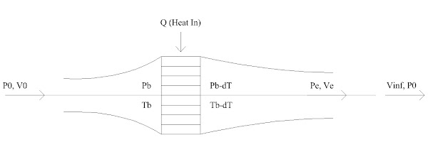
To tweak it a little. Good cooling is efficient mass air flow thru the cylinder fins. The major driver of that is pressure differential and making the air go where you want it to.
")
If good cooling is efficient mass air flow, how is that efficiency defined?
There's plenty of air available in front of an air plane to affect cooling, so the amount used, as it is free, can't be the answer. It has to be the amount of drag created as the air enters and moves through the engine compartment. The basic premise here is that increasing air flow through the RV engine compartment results in more drag. That may not be true at the speeds we fly at and the compromised shape of the cowl itself to accommodate the engine.
Seems like if inlet air is restricted because of internal pressure caused by a small exit area, drag is created in front of the engine compartment as oncoming air creates a wall of pressure at the inlets and spills over the top, bottom and sides of the exterior of the cowl. It has no where to go so that's what happens. The front of the cowl is not continuously smooth with its inlet holes, there is a radical cowl shape change from near vertical to near horizontal, and there is a spinning prop stirring things up to boot. This is not a drag free environment and there may be more drag with less air entering the engine compartment.
If pressure within the cowl is low due to a large exit area, air enters the cowl, removes heat, and passes on through. It is assumed this creates more drag than oncoming air deflected around the cowl due to a restricted exit area and I question it. I have a hard time believing it makes much difference at the speeds we fly.
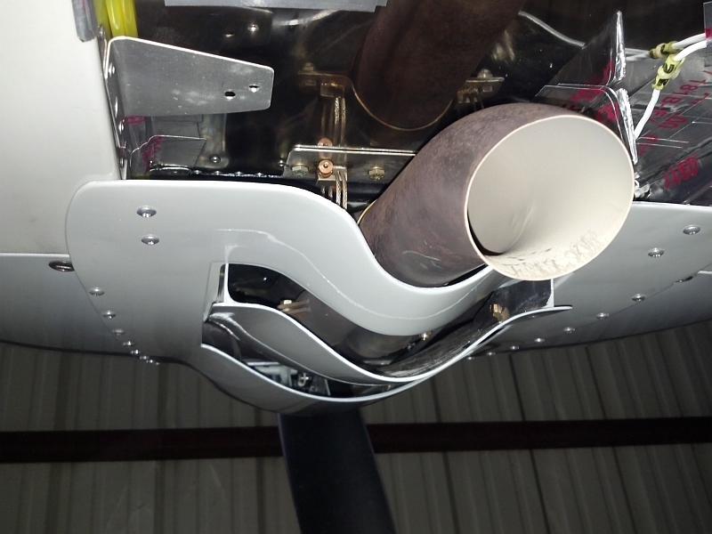
The increased drag (if any) created by a 219% exit area is not significant. The airplane goes as fast as the published numbers at Vans and the up side is very good cooling. It would be most disappointing to close the cowl to original specs, not fly any faster, and maybe have cooling issues. Seems like a not brainer to leave it alone as is.