What's new
Van's Air Force

Don't miss anything! Register now for full access to the definitive RV support community.

7A elevator spar crack

I've always believed...

That those locknuts on the rod end bearings, once tightened and torque- sealed, would never come lose without visibly breaking the torque seal. Yesterday, I found myself shaken to the core, seriously. I always visibly look at the locknuts on the all control surfaces during a preflight for just that, and I routinely touch most, but not all of them. Well, yesterday, after 720 hours on the Hobbs, I checked the tail a little more closely and I found one on the left elevator, and one on the rudder that I turned with my fingers during the preflight!
My rudder also had some wind damage about 2 years ago due to a thunderstorm.
Related? Will never know. But I will certainly keep an eye on the jam nuts a little more closer.
As a further note, I have been a DAR on many rv's in the last 5 years, and I have only found 1, yes one, that didn't have some loose jam nuts on the tail rod end bearings. This seems to be a regularly overlooked area.

Vic
 
Just another data point

RV-7 340 hours, IO-360-M1B. Gave it a quick inspection when this thread first opened up and didn't find anything. I had used torque seal and look at it during preflight. Went back today and really gave it a good going over with the flashlight and mirror. Cleaned the area and looked for cracks. Tugged and wiggled, thoroughly. Everything seemed to move smoothly with no discernable flexing or binding. Put a wrench on the lock nuts and they were tight on both the elevator{s} and rudders. Checked the trim servo and hardware. It was fine. Celebrated by putting air in the tires and going flying, Even did a roll and a few wheel landings. :D

This is a good thread, guys! Thanks for the heads up. This is what keeps me reading VAF even though the plane has been flying 5 years.
 
Last edited:
ANOTHER INSPECTION REPORT

G'day folks,

RV-7, built to plans, 93 hours TTIS. 210 landings, 50:50 sealed:unsealed surfaces.

Inspected tail cone & empenage:
both vertical & horizontal stabs felt solid - no movement or noise detected.
free movement of control surfaces (no differential movement of elevators).
no cracks noticed.
slight movement of elevator trim tab, as reported in other posts, and slight noise with movement coming from manual trim cable moving in plastic snap bushing at rear H stab spar.
All rivets OK, nuts tight, BUT, torque had relaxed on the four nuts holding the front Horizontal (and front vertical) stabiliser through shims to the fuselage rear upper deck. All retorqued - my impression is that the two outer nuts had relaxed slightly more than the two inner nuts - not much movement of the wrench before reaching the torque setting on any of the four (torque seal remained intact to my eyes - so wrench needed to confirm - seal only good as a indication that the nut has been tightened - not that it has retained its correct torque).

Thanks for this thread and all the contributors. This site has to be the best value in aviation - so thanks and much appreciation too for Doug Reeves.
 
That those locknuts on the rod end bearings, once tightened and torque- sealed, would never come lose without visibly breaking the torque seal. Yesterday, I found myself shaken to the core, seriously. I always visibly look at the locknuts on the all control surfaces during a preflight for just that, and I routinely touch most, but not all of them. Well, yesterday, after 720 hours on the Hobbs, I checked the tail a little more closely and I found one on the left elevator, and one on the rudder that I turned with my fingers during the preflight!

This is precisely why I have said many times that a dab of torque seal means nothing to me when doing an inspection, its presence does not guarantee proper torque, only a wrench can do that.
 
6 out of 7 stop nuts loose

1993 RV-4, 0320, @1000 hrs., 3rd owner, not builder. Have owned plane for @500 hours and, honestly, never knew to check rod end bearing stop nuts for tightness. Nor, apparently, did my A&P who did annual conditional inspections. :eek:

Found 6 of 7 stop nuts loose on tail. Tightened all and plan on adding torque lines (even while recognizing last post that even if torque line discloses no movement only a wrench confirms for sure the nut is still tight).

Unable to find evidence of cracks on either HS/VS side or elevator/rudder sides of attachment points. (But they are both well-painted, so I'm not sure if cracks would necessarily show(?).)

No play of any kind between right and left elevators.

Thanks a lot to all for this thread.
 
I'd want to see the actual parts, or see some better pictures, but this crack doesn't look like a typical high cycle fatigue crack to me. Cracks like to start at (not near) holes or edges and grow towards other holes or edges. My thought I'd that looks like low cycle fatigue, with a small number of VERY high stress events causing this weird crescent shaped crack just under a fastener, which could be caused by very high bending loads in that fastener.

From other posts, it sounds like this tail saw some kind of wind or impact event on the ground?
 
It's hard to tell from the earlier photo's but it would be worth verifying that the cracked spar has the grain direction running correctly to the bends of the spar. On my RV6 the grain is running perpendicular to the long bends of the spar. I think if the grain was running parallel to the bends, cracks could develop easier. It's not impossible that a operator could have sheared a sheet the wrong direction.

Looking closer at the photo with the paint stripped it really looks like the grain is running the wrong way.
 
Last edited:
tool required?

I've been following this tread with great interest, and came to think of one thing regarding thightening the loose locknuts: schouldn't the rod-ends be held in position with a tool during the tightening?
If not, I guess the rod end ball-bearing will be exposed to pretty heavy forces?

When tightening the rod ends during the build, I used a special tool bought from Avery.
This tool will keep the tightening forces to the rod end casing and not the bearing.

In order to use it, the control surface must be removed, so the job gets alittle more complex, but certainly doable.

Here's a link to the tool:
http://www.averytools.com/prodinfo.asp?number=408
 
If there was a general issue with the design, it would have become evident many years ago. At the very least, on RV-8's. They use the exact same (prepunched) elevator.

I said it once, but I guess many don't believe... this type of a crack does not occur from one (or even several) overload/bend events localized at the crack. It is many (probably many thousands, possibly even many ten thousands) load cycles. The damage from a single overload in a location like this would be a visible crease or bend. Not an original flat surface with a (fatigue) crack.

Deductive reasoning says that something has been causing a localized load cycle on this (maybe these two) airplane, that does not occur on thousands of others that have much more flight hours on them. The challenge is discovering what. Once we know that, a solution is right behind.

My opinion is that we haven't yet heard all the details.

I've quoted the above merely because it would be good it everyone read it again. Scott makes four fundamental points. I think we have general agreement on 1, 3, and 4. Some debate remains regarding #2, the question of low-cycle or high-cycle loading. Serious addressing #4 would do wonders for settling that question. Gathering all the details is the hard part.

Let's keep it focused. Problem solving in an internet forum tends to be like a Dick Cheney quail hunt; shotgun fashion, in random directions, with poor results. It is fine to propose a theory, but the theorist should be able to offer evidence or a logical path to the conclusion. For example, you could say "It cracked because aliens fired a destructo-ray from orbit". However, without evidence of aliens or destructo-rays or unidentified orbiting objects, the proposal is useless. Please include how you came to the conclusion; evidence, math, logic, a link to an SAE paper on destructo-rays, whatever demonstrates some thoughtful analysis. Heck, even if wrong we'll probably all learn something useful in the process.

Returning to #4, Mark, Bill K, can you confirm the dimension in the drawing was 7/8" or less? I realize you may have dismantled the offending elevator, but the other one should be similar.

juenfo.jpg
 
Rod end measurements

Dan,
I measured the right elevator rod ends before dis-assembly.
I used a pocket scale only. They were both identical using a scale.
I'm at work now but I remember what I wrote down. 7/8 minus 1/32.
So it's 27/32.

I won't be able to go to the airport until tomorrow afternoon.
I will check the left elevator alignment like Alex suggested.
Then I will pull it and check the horizontal stabilizer hinge point alignment.

I should finish getting the skin rivited on my new elevator spar this evening.
I finished the internals last night.

Mark
 
Mark, I suppose it sounds cockeyed to some and I didn't supply SAE analyses but grain direction in sheet metal makes a difference. Check it out...
 
Mark, I suppose it sounds cockeyed to some and I didn't supply SAE analyses but grain direction in sheet metal makes a difference. Check it out...

From the pictures, I agree, it looks like the grain runs outboard-inboard. I'm also more convinced that it's not a fatigue crack, the path is all wrong, fatigue cracks wandew from hole to hole like a river, this is too smooth and symmetric to be a fatigue crack. I think there was some combination of local bending (from that rivet) and tension and shear in the web that caused that. That doubler is REALLY thick compared to the spar, so the rubber has to potentially trader a lot of load.

I'm not convinced that that crack would be a problem under normal usage, unless a fatigue crack started to grow from there and became very long, because that doubler is more than capable of taking any load in that area. The elevator spar doesn't really have to do that much, most of the lift is made at the leading edge of the HS. The loading on the elevator is mostly torsional (the aerodynamic force during deflection is reacted only at the inboard end of the elevator (or canceled by the trim tab)), which shows up as shear in the whole spar. Most spars see a lot of tension/compression in the caps and shear in the Web.

That said, this crack is a great place for a fatigue crack to form, so it absolutely needs repair.
 
If the bearings are in alignment, then one other option for such a load being applied to the bearing IAW Dan's drawing is if the hinge bracket binds on the elevator skin (at this bearing) before the elevator reaches the stop. So when the elevator is on the full up stop (common for me when taxiing) the interference between the skin and the bracket will load the elevator spar in this way.

I have a very dim recollection of having to remove a mm or two off the skin/spar flange at this point to clear the bracket at full deflection, but my Pre punched 6 kit may be different.

Mark, can you check for any witness marks on the skin and brackets.

A long shot, but another possibility.
 
Update

Ok, on the left elevator I moved it full up and full down and could not tell any difference in how the bolts slid in and out in each position. Alex suggested I try that to check for alignment.

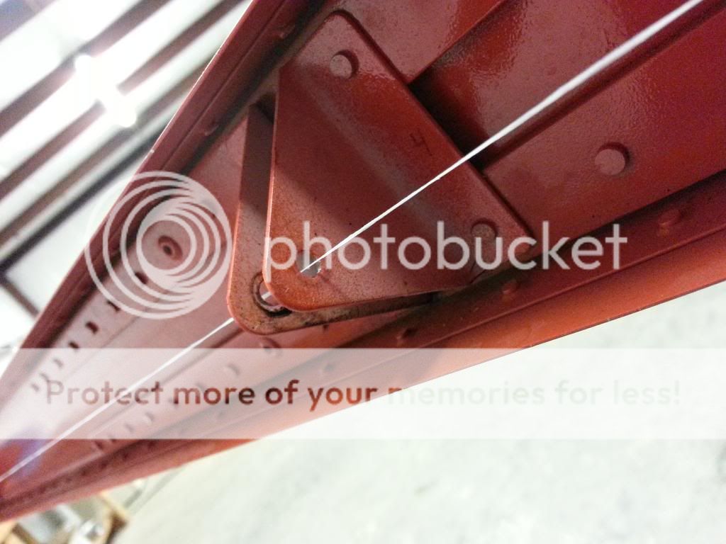
I removed the left elevator and ran dental floss through the attach brackets on the horizontal stabilizer all the way across. This is something F1Boss recommended checking. I was worried about this because a fix would not be easy.

The stabilizer checked perfect! Whew!

20130930_191452.jpg


Then I ran the dental floss check through the horn and two bearings of the left elevator, and it was perfect also. As much as the naked eye could tell.

I dye checked the left elevator outboard rod end area and no cracks found.

I wished I had checked the right elevator alignment better before I dis-assembled it but I really doubt that was the problem.

As far as the grain of the aluminum being the wrong way that someone mentioned. I lightly ran purple scotchbrite over all the internal components before priming. So, seeing the grain looks difficult to me.

One other thing that hasn't been mentioned, (I don't think) is how the right steps on the RV-7A's crack way more often than the left side. And now we have two right side elevator spars cracked. How can we be getting some bad "vibes" on the right side?

And finally, I think I know what caused the "crease" in the spar at the edge of the doubler. I was looking at the old doubler last night and noticed it was slightly curved, especially on the corner that was next to the dent in the spar. I think it was that way from Vans because the new one was curved also but to a lesser degree. And after looking the spar the word "crease" is a bit strong. More of a dent with an extended mark.

With the doubler being a bit curved I can see how bucking the rivets could possibly have caused the dent. There was no evidence of a bucking bar slip.

The spar replacement has gone well. I'm really good at drilling out rivets:D
I only have a few rivets left to install and the new tip is due here tomorrow.
A few days of fiberglass work and painting and I'll be good to go!

Mark

Didn't the crack occur on the spar of the right elevator?
Did you check the bracket alignment on the right side of the horizontal stab.?

BTW, from your photo it doesn't look like the alignment is perfect (it is slightly low in the hole, but that could be sag in the thread)
 
Last edited:
Didn't the crack occur on the spar of the right elevator?
Did you check the bracket alignment on the right side of the horizontal stab.?

BTW, from your photo it doesn't look like the alignment is perfect (it is slightly low in the hole, but that could be sag in the thread)

Rvbuilder2002,
Yes, the crack was in the right elevator. But I'm checking the left one.
Like I said in my post, I went ALL the way across the horizontal stablizer.

It's difficult to get a photo that looks right. The floss was centered.

Mark
 
Rvbuilder2002,
Yes, the crack was in the right elevator. But I'm checking the left one.
Like I said in my post, I went ALL the way across the horizontal stablizer.

It's difficult to get a photo that looks right. The floss was centered.

Mark

Palm on forehead... Sorry, You wrote removed left elevator to test, so I totally read passed the "all the way across" part...
 
...BTW, from your photo it doesn't look like the alignment is perfect (it is slightly low in the hole, but that could be sag in the thread)

It's very difficult to show alignment in a single photograph. Parallax will get you one way or the other. To document with still photos, take one from the front as directly as possible and still see the hole, and another from above or below, in a plane as close to 90 degrees to the first as practical.

To mitigate the sag problem I use nylon sewing thread; it's very light and very strong. Also, it's only a few thousandths in diameter, so there's no need to interpolate across the width of a piece of dental floss.
 
fishing line?

Wouldn't fishing line be a good substitute for the dental floss? Fishing line is strong and it can be pulled tight to get no sag. It seems you could get a better idea of hole alignment with the smaller diameter fishing line too.

It's very difficult to show alignment in a single photograph. Parallax will get you one way or the other. To document with still photos, take one from the front as directly as possible and still see the hole, and another from above or below, in a plane as close to 90 degrees to the first as practical.

To mitigate the sag problem I use nylon sewing thread; it's very light and very strong. Also, it's only a few thousandths in diameter, so there's no need to interpolate across the width of a piece of dental floss.
 
I tend to think a laser pointer would make a better gauge... set it up at one end, and hold a piece of paper on the opposite side of the mount from the laser. You'll see the whole hole illuminated, and the laser spot will show up in the middle. Then go to the far end, and repeat. A few iterations will get the laser aligned with the outer two mounts, then you can check the inner mounts the same way. That's how I aligned mine.
 
I've been away from this board for many months, but now playing catch up for the last few days and come back to see this thread. Y'all sure know how to spook a guy. I sure hate to hear the loss of one of our own over this too even more disheartening that he was a member on this forum.

I appreciate the OP starting it though, and for those stating to also check the nuts at the attach points along with looking for cracks. These type of threads are the most important of all, and can be lifesavers.

I have a 6 with a counter-balanced 8 rudder on it, not sure about the elevator. I looked at the necessary attach points on the elevator and rudder. I looked from up top looking down for cracks, then got the creeper out, and spent some time on my back looking up at the upper area. No cracks found. Did find a loose nut on the outer left elevator that was about an 1/8 of a turn out. Also had another loose nut on the bottom of the rudder also about an 1/8 of a turn out. Just snugged them up like what was suggested, and this time put a witness mark on all as well. I'll be working on a custom tool to get to those nuts easier.

Thanks to everyone that participated in this thread even though it has caused me some sleepless nights. I’ll be paying more attention to this area than ever before.
 
I check my jam nuts, all of them, at CI. Never seen one loose. Checked again last night, none loose, no cracks, and didn't expect to see any.
Glad for the original OP, but as far as I can see, this is a one off situation and nobody really knows why.

As far as bearing alignment, hundreds of us did it with a string. I bet there are a lot more than a few that are something less than perfectly aligned. These things should be cracking all over the place if that was an issue.

Some good things have come out of this thread though. A few loose jam nuts needing tightening and some other elevator construction or maintenance issues, so again, glad to see these posts anytime something odd comes up.

Special wrench? The aviation community has managed without one, well, since pretty much forever..... I really don't find it to be that hard to get a wrench on them, and if you are checking your jam nuts like you should, at every CI, you also may never find a loose one.
 
Special wrench? The aviation community has managed without one, well, since pretty much forever..... I really don't find it to be that hard to get a wrench on them, and if you are checking your jam nuts like you should, at every CI, you also may never find a loose one.

I didn't build mine, so have to have an A&P do my CI's, but now that I know better, I will be checking this area much more frequently for cracks and loose nuts.

My open end wrench is flat, no angle on it, and prevents me from getting a really good bite on the nuts. Just not much room to work with. I have to come in at a 45 degree angle or so, and felt like I got it snug, but I could be getting a much better bite, and can see doing it like this over time will eventually butcher up the nuts. There isn’t much room to work with. What wrench do you use?
 
I didn't build mine, so have to have an A&P do my CI's, but now that I know better, I will be checking this area much more frequently for cracks and loose nuts.

My open end wrench is flat, no angle on it, and prevents me from getting a really good bite on the nuts. Just not much room to work with. I have to come in at a 45 degree angle or so, and felt like I got it snug, but I could be getting a much better bite, and can see doing it like this over time will eventually butcher up the nuts. There isn?t much room to work with. What wrench do you use?

I have an S&K set. They are thinner than Craftsman or other similar types but you are right, they do not fully engage the nut across the entire flat. They work fine for me.
In general, I don't feel the need to have a special tool for everything that I will use for only one purpose, once a year, that gives me very little, if any, added value. But that is just my opinion. There are companies making an entire business out of selling this type of stuff, so don't listen to me! If you see the benefit, you should do what you feel is right for you.

Hey JJ...I may have to revoke your man-card over this one buddy ;). Buying (or making) a tool that you only need once a year (or heck, just once) is one of the simple pleasures of this hobby. Another is when your friends ask if you have one of those rare "umptifratz" tools, and you get to say, "why yes, of course I do!" :p

Then again, spending the $ on avgas is pretty cool too. I guess we'll have to find a balance of simple pleasures! :)

Cheers,
Nasty
 
Buying (or making) a tool that you only need once a year (or heck, just once) is one of the simple pleasures of this hobby. Another is when your friends ask if you have one of those rare "umptifratz" tools, and you get to say, "why yes, of course I do!" :p

Exactly!!

Heck, I have tools I have never even used, and tools I have no idea what they are even used for--------but, I got em:D:D
 
The RV-3B doesn't have a lot of room for the more common tools to engage the jam nut, and I'd certainly pay for a dedicated tool for the job.

Dave
 
Here's the tool I made for the nuts, hurts to cut up a snap on but it was for a good cause :eek:
P/N: XS1618

Misc-wrench.jpg
 
Hey JJ...I may have to revoke your man-card over this one buddy ;). Buying (or making) a tool that you only need once a year (or heck, just once) is one of the simple pleasures of this hobby. Another is when your friends ask if you have one of those rare "umptifratz" tools, and you get to say, "why yes, of course I do!" :p

Then again, spending the $ on avgas is pretty cool too. I guess we'll have to find a balance of simple pleasures! :)

Cheers,
Nasty

Fair enough buddy. Ha!
I think Walt gets two man cards for cutting up a perfectly fine snap on, but he is a pro, and see's more than his fair share of nuts! :D
 
Fair enough buddy. Ha!
I think Walt gets two man cards for cutting up a perfectly fine snap on, but he is a pro, and see's more than his fair share of nuts! :D

All man-cards safe! ;)

Now to cut up a tool (but not a Snap-On) :)

Cheers,
Bob
 
Don't forget the other tool!

The other part of the equation is a tool for holding the body of the rod end straight, i.e. perpendicular to the hinge axis. A tube of the right diameter, with a slot of the right width, with a t-handle rod on the other end, would be great.

wouldn't it be nice if someone else did all the measuring, figured out the right size, and sold them?

Easily made from PVC pipe fittings. First appeared on RV builders' sites about 16 years ago. Mine is hanging on my shop pegboard. No need to buy one.
 
Someone around here does sell them actually...I ended up with one when I bought all my tools from lots here on VAF. :)
 
The other part of the equation is a tool for holding the body of the rod end straight, i.e. perpendicular to the hinge axis...

In a pinch, cleco pliers work pretty well too. They grab the head of the rod end without marring the body or touching the ball.
 
I just use a flare nut wrench. They are similar to what you made, but beefier walls to withstand the fact that they are open. No need to damage a fine tool when you can buy just what you want.

Dan
 
What am I missing?

Other than the cool factor, why not use a plain open end wrench? Many, really many, years ago, when my tool budget was just going from zero to minimal, the first wrenches I bought were combination type, just because sometimes fuel lines and rod ends and similar stuff would not allow the box end to fit.
 
hey just think what it would have cost if you had snap on make that for you.:eek:
i have had to make new tools out of what i had alot cheaper to make them and buy a new one:D
 
And is the coolness factor a constant? Hmmm...

Thanks, Bob K.

Now that's funny right there Bob! ;)

But no, its not a constant. If its a snap on, you divide the length of the wrench (in mm) by the angle of the bend in the handle (in radians) and apply that number to...oh never mind...lets just call cool a constant! :p

Crows foot and a home-made bearing holder that my next door neighbor has is what I used when I built and switched to an 8 tail. But I can't get in there when he's gone, so I need those specialty tools (that's what I'm gonna tell my wife anyway!) :rolleyes:

Cheers,
Bob
 
I'm sure there is already a tool out there that would work, it's just a matter of finding out what it was originally intended for. The box of tools I inherited from my auto mechanic father includes a lot of ? tools that were for some special purpose. Among them are offset distributor wrenches, belt tensioning adapters, etc. such as this, which would probably work if it was 9/16":
http://www.ebay.com/itm/KD-Tools-3256-Belt-Timing-Belt-Tensioner-Adapter-NEW-/321103557240?pt=Motors_Automotive_Tools&hash=item4ac3437278&vxp=mtr

or this, with a cut:
http://www.ebay.com/itm/vintage-SNAP-ON-9-16-Exhaust-manifold-torque-wrench-adaptor-S8681-USA-1-2-Drive/281178046899?_trksid=p2047675.m1850&_trkparms=aid%3D222002%26algo%3DSIC.FIT%26ao%3D1%26asc%3D17514%26meid%3D1770994929812686837%26pid%3D100011%26prg%3D8141%26rk%3D1%26rkt%3D5%26sd%3D151129738704%26

so who out there knows what tool is like the snap-on s8681, but with a 3/8" drive?
 
dumb question

I'm not flying yet, so forgive me if this is a dumb question. When you all are checking the jam nuts, are you first removing the control surface?
 
I'm not flying yet, so forgive me if this is a dumb question. When you all are checking the jam nuts, are you first removing the control surface?
It's a bit easier with them off, Dave, but it can be done with them on. The trickiest part is hold the rod end square whille you're tightening the jam nut. Harder to do with it's inserted into the HS hinge. As an aside, I used blue loctite when I first torqued them and haven't had any loosening issues. Blue loctite is pretty strong.
 
Back to the rudder

This discussion is excellent timing for my build as I am finishing mounting my tail. I have written down several items to double check. One question that I have concerns the rudder.

When the aircraft's rudder was damaged by the wind, the rudder stop was ripped from the aircraft. A few folks have mentioned wind damaged rudders. It seems prudent to inspect the rudder spar and the VS spar. That is a lot of force transmitted through the rudder horn into the spar and it's hinge points.

Please do not interpret this as speculation on an accident. It is not. Just trying to further my knowledge.
 
I don't know the "normal" procedure, BUT when I do my tail group inspection.

I do everything from the tail strobe to the baggage bulkhead. If I try to do just a portion, I'll most likely forget something. so it' all or nothing for me.
 
Back
Top