What's new
Van's Air Force

Don't miss anything! Register now for full access to the definitive RV support community.

I think I have uneven airflow....

this preliminary data shows that the stock up draft sump that many think is the evil for air distribution, really flows air quite well.

Don

Good information Don!

I really would be interested in flow bench data for my stock updraft 540 sump.
 
Here is another data point.

We are currently developing a fuel injection kit that will fit in the stock Van?s 320 cowling without modifying the cowling. Our test bed was an RV-6 with a Titan 340 engine. The stock configuration was with an MA-4 carburetor (although the sump looked like a stock 360 sump to me). Data from the GRT down load on previous runs with the carb. gave the following:
T.O. power of 2624 RPM and 29?MAP around 15 GPH with EGT?s of 1445, 1411, 1265, 1223 (cyls. 1-4 respectively in degrees F.). At a cruise power setting of 2600 and 24?and 11.3 GPH with EGT?s at 1215, 1213, 1318, 1305. All data here was full rich

With no changes to the engine other than bolting on a FM-150L with stock injector nozzles we install on a 320 (all the same size) and installing the necessary high pressure engine driven pump, aux pump and a new inlet filter air box we got the following. Take off power 2600 RPM and 28.5? MAP fuel flow was 15.7 GPH with EGT?s at 1274, 1294, 1251, 1298. Cruise power of 2400 and 24? fuel flow 11.4 GPH with EGT?s at 1225, 1268, 1217, 1249. Again all data here was full rich

Checking the full rich to peak EGT at 24 square gave a change of around 230 degrees F. Indicating the fuel control was set plenty rich. This gives a F/A of around .089 (or for you car guys 11.2:1). A quick lean to peak curve was run at 24 square to check the GAMI spread. This was by no means really accurate because the time to lean was only around 45 seconds( normally to get accurate data, EGT needs to sit on a data point for 30 seconds then lean 0.2 GPH etc.), but GAMI spread was 0.3 to 0.1 GPH. This was only run to 50 degrees LOP with smooth operation.

While we are still improving our filter box to get rid of some flow loses this preliminary data shows that the stock up draft sump that many think is the evil for air distribution, really flows air quite well. Can there be improvements; probably. But the gains probably won?t be noticeable in a flight situation. Even with tuning the injector nozzles we probably will not see an improvement in power, with only a slight improvement in fuel economy.

This was a pretty simple install, no programming, no jet changes, just straight up bolt on and set the idle mixture.

So, more to come as we complete this project with the final design of the air box and gather additional real flight data.

Don

Interesting data. I'd usually expect the EGT spread to be less with the same engine/manifold using fuel injection of any sort since you are flowing dry air and not wet charge.

My take on this is that some combinations are better than others and that heads and manifolds together may create imbalances in mixture distribution. The Titan heads may be more closely matched in flow than Lycoming ones as we often see much larger spreads on other updraft examples- 170-200F with carbs and with EFI, still pretty large spreads where we're pretty sure injector flow rates are near equal since we've swapped injectors over to the other bank with little change.

The combination you are testing clearly works pretty well.

I welcome more test data and especially from anyone using a Sky Dynamics intake. I hope on a future project we may be involved with to get some dyno numbers on that combination. Always interesting...
 
My take on this is that some combinations are better than others and that heads and manifolds together may create imbalances in mixture distribution.

So you're dismissing this data set as mere luck.

The Titan heads may be more closely matched in flow than Lycoming ones as we often see much larger spreads on other updraft examples- 170-200F with carbs and with EFI, still pretty large spreads where we're pretty sure injector flow rates are near equal since we've swapped injectors over to the other bank with little change.

Although there is undoubtedly some variation in flow capacity between randomly selected heads of any brand, it is probably not so large as we're being led to believe. Maybe Don's customer just got lucky, but gee whiz, GAMI spreads of 1 GPH or less are pretty standard right out of the box with constant flow injection. My own was less than 0.4, and only required one restrictor 0.0005" larger and one 0.0005" smaller to balance.

May I suggest an entirely different explanation?

As demonstrated, wet flows and dry flows are not at all the same. Until fully in vapor phase, fuel tends to follow its own path when airflow changes direction.

As currently configured, the EFii injectors are located on the intake runners, pointed downward, perpendicular to the crankshaft centerline. However, the individual intake runners intersect the injector spray pattern at either four or six different angles in two different planes (approach angle and runner bend), at the curve in the runner. The result is entirely non-symmetrical; no intersection of fuel spray and airflow is the same.


Although much is made of an electronic injector's "highly atomized fuel spray", it is useless if a high percentage of those tiny fuel droplets fail to reach vapor phase, or clump back together into larger droplets, or simply wet the walls of a relatively cool manifold runner. Those are classic problems in the wet flow from a carb or single point injection, and I suggest that the EFii injector placement (below, A) is subject to the same.

The vast majority of port fuel injection designs (mechanical or electronic) place the injector so that it sprays fuel at the back side of the hot intake valve (C). The combined heat and pressure drop at valve opening instantly flashes the fuel to vapor, even if pooled there.

Re-positioning the electronic injector, either to an optimum position on top of the head (C, the standard Lycoming injection port), or to a less optimum but still better position pointed up into the intake port (B) might prove to be a worthwhile experiment.

Of course, position (B) would tend to trap vapor bubbles following a hot shutdown, and thus may negate a key benefit, simplified hot starting as compared to constant flow injection.

Further to injector placement, anyone who has ever played around inside a flowing intake port with a manometer probe knows that there are significant pressure variations at various points, notably around curves. Here, fuel delivery is dependent on deltaP between the fuel rail pressure and the manifold pressure in the immediate vicinity of the injector. The fuel pressure regulator varies rail pressure to maintain deltaP, but necessarily assumes that manifold pressure is the same in all runners. Variations in local manifold pressure would result in variations in fuel delivery at individual injectors.

 
Last edited:
So you're dismissing this data set as mere luck.


Although there is undoubtedly some variation in flow capacity between randomly selected heads of any brand, it is probably not so large as we're being led to believe. Maybe Don's customer just got lucky, but gee whiz, GAMI spreads of 1 GPH or less are pretty standard right out of the box with constant flow injection. My own was less than 0.4, and only required one restrictor 0.005" larger and one 0.005" smaller to balance.

May I suggest an entirely different explanation?

As demonstrated, wet flows and dry flows are not at all the same. Until fully in vapor phase, fuel tends to follow its own path when airflow changes direction.

As currently configured, the EFii injectors are located on the intake runners, pointed downward, perpendicular to the crankshaft centerline. However, the individual intake runners intersect the injector spray pattern at either four or six different angles in two different planes (approach angle and runner bend), at the curve in the runner. The result is entirely non-symmetrical; no intersection of fuel spray and airflow is the same.


Although much is made of an electronic injector's "highly atomized fuel spray", it is useless if a high percentage of those tiny fuel droplets fail to reach vapor phase, or clump back together into larger droplets, or simply wet the walls of a relatively cool manifold runner. Those are classic problems in the wet flow from a carb or single point injection, and I suggest that the EFii injector placement (below, A) is subject to the same.

The vast majority of port fuel injection designs (mechanical or electronic) place the injector so that it sprays fuel at the back side of the hot intake valve (C). The combined heat and pressure drop at valve opening instantly flashes the fuel to vapor, even if pooled there.

Re-positioning the electronic injector, either to an optimum position on top of the head (C, the standard Lycoming injection port), or to a less optimum but still better position pointed up into the intake port (B) might prove to be a worthwhile experiment.

Of course, position (B) would tend to trap vapor bubbles following a hot shutdown, and thus may negate a key benefit, simplified hot starting as compared to constant flow injection.

Further to injector placement, anyone who has ever played around inside a flowing intake port with a manometer probe knows that there are significant pressure variations at various points, notably around curves. Here, fuel delivery is dependent on deltaP between the fuel rail pressure and the manifold pressure in the immediate vicinity of the injector. The fuel pressure regulator varies rail pressure to maintain deltaP, but necessarily assumes that manifold pressure is the same in all runners. Variations in local manifold pressure would result in variations in fuel delivery at individual injectors.


There's a big difference between .2 and 1 GPH GAMI spread, so yes, I'm saying in this case, the planets align better than the typical case.

The rest of your post, agree. Injectors should be aimed at the port as 99.999% of engines do.

With regards to manifold pressure variations affecting injector flow on a plenum type manifold running at or near WOT, we recently scoped a runner for MAP variation during the cycle on a 4 cylinder test engine. The mean variation to the test runner with the other 3 (common plenum manifold again) saw about a 10-12% difference over a 2-3 mS. This relates to about .5psi worst case and since fuel pressure is around 40-45 psi and fuel flow varies as the square of the pressure, you can see this would have little effect on flow (less than 1%), especially in cruise where the injector pulse width might be 10-15ms.
 
Last edited:
I'd sure like to hear the reason why the injectors are aimed "upstream" as well. That seems completely contrary to everything I know (which isn't saying much), but I'd love to learn something new.
 
Re-positioning the electronic injector, either to an optimum position on top of the head (C, the standard Lycoming injection port), or to a less optimum but still better position pointed up into the intake port (B) might prove to be a worthwhile experiment.

Is there anything that would prevent an injector from being installed in the "standard" port, besides possibly the lack of a specific adapter?

Of course, position (B) would tend to trap vapor bubbles following a hot shutdown, and thus may negate a key benefit, simplified hot starting as compared to constant flow injection.
Not being familiar with fuel injector construction, wouldn't any backpressure from the vapor bubbles be able to relieve itself into the common fuel line, and wouldn't any vapor in the injector itself get bled out in the first couple of injector pulses when cranking?
 
Is there anything that would prevent an injector from being installed in the "standard" port, besides possibly the lack of a specific adapter?


Not being familiar with fuel injector construction, wouldn't any backpressure from the vapor bubbles be able to relieve itself into the common fuel line, and wouldn't any vapor in the injector itself get bled out in the first couple of injector pulses when cranking?

Yes, the injector is too large and the cone of spray too wide to be installed here without mods. Second concern is the high temps on the head casting. Automotive injectors are not validated to work at 400F. Aerosance had issues with hot starting with injectors mounted in the heads directly.

With EFI, you never want vapor in the rail as the fuel metering is garbage then. It takes a while to bleed the hot fuel out of the injector during cranking and the first few seconds of idle but with a loop/ rail type setup, all hot fuel is purged immediately from the rail when you turn the pump on with the usual return type system and as soon as the pump pressurizes the system (about 1/2 second), usually the boiling fuel immediately stops boiling anyway.
 
....so yes, I'm saying in this case, the planets align better than the typical case.

Ahh, the Lucky Sump Theory ;)

Yeah, I'm pulling your leg...a little.

Injectors should be aimed at the port as 99.999% of engines do.

So, to repeat Mike's question, why are they pointed down in this installation?

With regards to manifold pressure variations affecting injector flow on a plenum type manifold running at or near WOT, we recently scoped a runner for MAP variation during the cycle on a 4 cylinder test engine. The mean variation to the test runner with the other 3 (common plenum manifold again) saw about a 10-12% difference over a 2-3 mS.

If I understand the above test correctly, you connected one leg of a dual trace oscilloscope to a fast response pressure transducer on one manifold runner, and the other trace to a similar transducer mounted on the manifold's common plenum?
 
Ahh, the Lucky Sump Theory ;)

Yeah, I'm pulling your leg...a little.


So, to repeat Mike's question, why are they pointed down in this installation?


If I understand the above test correctly, you connected one leg of a dual trace oscilloscope to a fast response pressure transducer on one manifold runner, and the other trace to a similar transducer mounted on the manifold's common plenum?

Robert chose to point the injectors against the flow and against convention for reasons unknown to me, perhaps cowling clearance in some installations. I've voiced my concerns about this on numerous occasions...

We took readings with a scope while doing some R&D a few weeks back for a new project. Just looking at the transducer signal in the runner and the 3 "shadow" pulses from the other 3 cylinders for a difference in waveform and amplitude.
 
injector angles

There are two reasons why we point the injectors the way we do.
It prevents fuel rail vapor bubbles from getting trapped at the injector valves after shutdown and it provides more energy to the fuel spray during operation.
You have to keep in mind that these are 1/2hp per cu in engines. Air flow velocities are low.

We tried every injector angle/position possible before standardizing our setup.
Dyno results just in yesterday from Sky Dynamics showed a 6hp increase on Tye Berry's RV-10 engine when running our system over their mechanical injection system they use for break-in. (540 angle valve, 9:1 comp, cold air, just under 300hp peak with EFII). Sky Dynamics also reported very easy starting and very smooth operation with EFII.

Robert
 
Last edited:
Just looking at the transducer signal in the runner and the 3 "shadow" pulses from the other 3 cylinders for a difference in waveform and amplitude.

Got it. Good stuff and certainly valuable, but doesn't address the concept I was trying to communicate.

Here's an expanded example. Assume three intake tubes, one with a 90 degree bend, one with a 45 degree bend, and one straight. Attach a pressure tap to each (like where one might place an injector), here just above the bends in the first two. Run the same air velocity and density through all three, and consider the flow at the bends. Think you'll get the same pressure reading for each, or three different local pressures at the tap points?


There are two reasons why we point the injectors the way we do.
It prevents fuel rail vapor bubbles from getting trapped at the injector valves after shutdown and it provides more energy to the fuel spray during operation.

Robert, could you please expand on "provides more energy to the fuel spray"?

You have to keep in mind that these are 1/2hp per cu in engines. Air flow velocities are low.

Hmm. Runner velocity is not a function of HP. For Clark's 370 at 2700 RPM, velocity would be about 221 feet per second (150 mph) assuming a 2" diameter intake runner and 100% VE. It would be about 394 FPS (268 mph) for a 1.5" diameter runner.
 
Perhaps more shear by facing the injector into the airflow? More shear might better atomize.

Nope, atomization is effected by the velocity/pressure of the streams departing the orifices in the injector. Evaporation of the droplets takes place as they hurtle through the airstream, looking like little comets with streaming vapor behind them.

It might provide improved evaporation in the greater upstream volume of the intake tube during the period of the closed intake valve, but may impact the tube wall at that angle. Only a lot of money and time on multiphase CFD modeling or a bunch of test work (and luck) can tell what works best.
 
Last edited:
Interesting data. I'd usually expect the EGT spread to be less with the same engine/manifold using fuel injection of any sort since you are flowing dry air and not wet charge.

My take on this is that some combinations are better than others and that heads and manifolds together may create imbalances in mixture distribution. The Titan heads may be more closely matched in flow than Lycoming ones as we often see much larger spreads on other updraft examples- 170-200F with carbs and with EFI, still pretty large spreads where we're pretty sure injector flow rates are near equal since we've swapped injectors over to the other bank with little change.

The combination you are testing clearly works pretty well.

I welcome more test data and especially from anyone using a Sky Dynamics intake. I hope on a future project we may be involved with to get some dyno numbers on that combination. Always interesting...

Just another bit of info.

This is my plane/engine.

I worked with ECI using a variety of mods to the "standard" experimental carb for the 340 and a Van's O-320 airbox setup. The WORST CASE scenario had an EGT spread of almost 300 degrees!

ECI worked with me on various mods (using the constraint that it all had to fit in the O320 space with NO CHANGE to the older O-320 cowl that doesn't have enough space for an O-360 carb and airbox). We (ECI and I) decided to shift the effort to finding a fuel injected solution.

Since I know Don and he is nearby, I wanted to work with him on the answer (with ECI's support in finding a solution).

Over the last several weeks, Don and his team has been evolving the new design. I hope to visit again this week to do some more test flying followed by the testing of a further improved design.

It has been great working with them and I am looking forward to a much improved system (soon!). We will report the "improvements" here.

The 340 PULLS STRONG!!!!!

James
 
So, the numbers are in. I replaced my ECI updraft sump with the superior updraft sump. Unfortunately the numbers did not improve as much as I hoped. Here are the numbers from my test flight climbing to 8500':

ROP CLIMB

EGT's - 1220,1080,1215,1070
CHT's - 386,372,365,359

LOP CRUISE

EGT's - 1195,1260,1190,1280
CHT's - 352,397,334,384
GAMI - 1.2

So, the numbers are a little tighter and GAMI went down a little, but not enough to justify the money I spent on the new sump. Oh well. So, I need to look elsewhere to figure out the uneven airflow.

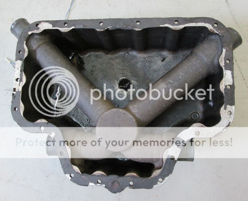
Do you have photos of the two sumps internally or any idea in the differences in plenum volume where the tubes all merge to?
 
That's pretty much it.

It's a pulse width modulated constant flow system, not a sequential injection system. All injectors open and close at the same time, and they are all supplied at the same fuel pressure, so all cylinders get the same fuel delivery, or better said, the same within the flow tolerance of the injectors. There is no way to modify fuel flow to any particular cylinder, so an owner is left with trying to modify the air delivery, or living with a huge GAMI spread.


A year and a half of heavily promoted Titan partnership, and nobody saw this on the dyno?

Most non-sequential systems have two "banks" and each bank is triggered from a differnt circuit. Most systems use a common open time for both banks, but I suspect some may allow variability in the open time for each bank. While difficult to set up, you could split the fuel feed into two circuits with independent regulators and use different pressures in each. With a common open time, it is not difficult to regulate total flow via fuel pressure. Set them them both at the designed pressure and slowly increase pressure in the lean bank until it evens out. Varying FP used to be a typical method of increasing fuel flow based upon vacuum in the early FI systems

Larry
 
Last edited:
Do you have photos of the two sumps internally or any idea in the differences in plenum volume where the tubes all merge to?

The superior sump's plenum appears to be more smoothed and polished than the ECI one, but besides that, hard to tell any difference.
 
The superior sump's plenum appears to be more smoothed and polished than the ECI one, but besides that, hard to tell any difference.

So the angles that the runner inlets connect to the common hole are not equal and no added volume at the collection point? Appreciate the back to back test. My theory is any sump with tube different angles and minimal plenum volume is unlikely to give near equal airflow. This is why I like the Sky Dynamics setups, plus they were developed with CFD which may be superior to the Mk 1 eyeball and intuition.
 
Last edited:
20 years or so ago, long before anyone knew about GAMI injectors a fellow wrote about his Mooney 231 that had a TSIO-360GB engine. These engines had such poor mixture distribution that if Continental got them back at the factory they changed all of them to an LB version with a better induction system. It was common during cruise with the GB engine to have 2 cylinders with CHT's 150*F higher than the coolest 2.

One gentleman who had a GB version (bad) took his induction tube gaskets where they attach to the cylinder flange and made smaller diameter gaskets for 2 rear cylinders a little larger for the middle cylinders and stock for the front. It was a bit crude but the engine ran much more even distribution with better CHT's temperature sspreads.
This was prior to any thoughts of LOP. The modification never received a multiple STC.
 
LOP operation has been around since the Mid '40s and so has bad mixture distribution...

We're working on an electronic "solution" for this issue.
 
The Wait is Over

Jan. 22 will see the release of V26 software featuring 100rpm increment programming and optional cockpit adjustable individual cylinder fuel trim for 4 cylinder engines.
 
Jan. 22 will see the release of V26 software featuring 100rpm increment programming and optional cockpit adjustable individual cylinder fuel trim for 4 cylinder engines.

SWEET! Will this software be useable in older EFII systems with the original ECUs?
 
SWEET! Will this software be useable in older EFII systems with the original ECUs?

We'll be able to do upgrades starting in Feb. on any EM-5 ECUs (produced after Sept. 9, 2011). Not applicable to EM-4 ECUs. If you have a programmer, you can check what board you have by powering up the system. In the initial bootup screen it will have the software version number- V17, V20 etc. You have an EM-5 board if you have V20 or higher. If you don't have a programmer, you can remove the top cover and look at the board series printed in large letters on the board. Anything starting with EM-4X is EM-4, anything with EM-5X is EM-5. EM-4 enclosures can have the board replaced with an EM-5 board in order to have the new capabilities.

There are minor wiring changes required (swapping pins on the white ECU connector) to synch ECU pins with the correct injector. Instructions will be provided by us.
 
Last edited:
Thanks. I will forward this information to my hangar partner. His EFII system is bout a year old and should have the EM-5 ECUs. His -7 is getting close to being ready for the first engine start.
 
Magic

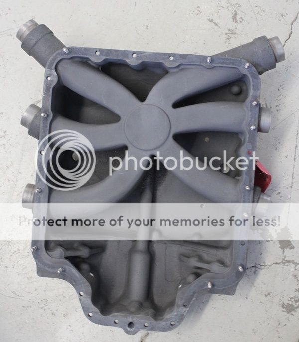
Here's what we're up against with typical vertical induction Lycomings:

540sump_zpsm7dxhs5t.jpg


Bad pairings, unequal shapes, small plenum volume and unequal runner lengths.

A recent test flight on a four cylinder with the fuel trim option had one cylinder at +2% and another at -9% to get all to peak at the same time. Was able to run at 200F LOP with uber smoothness.

Hopefully have more details soon.
 
Not magic, just facts

Of course that intake manifold was designed for a carburetor to be wet flowed. But even then, the most we see on most RV-10?s running that sump with our fuel injection (or Precision) is 1.5 to 2.5% total change in flow to get 0.2 GPH spread. On four cylinder up draft sumps it?s usually less than 1% to 1.5%. The Superior front sump is better. But the exhaust system plays a big role in the air distribution also. So if the engine you were working had an 11% (+2% to -9%) spread in airflow between cylinders then I would say that the engine was really screwed up. Or perhaps the fuel distribution was not equal, to begin with.
 
Of course that intake manifold was designed for a carburetor to be wet flowed. But even then, the most we see on most RV-10’s running that sump with our fuel injection (or Precision) is 1.5 to 2.5% total change in flow to get 0.2 GPH spread. On four cylinder up draft sumps it’s usually less than 1% to 1.5%. The Superior front sump is better. But the exhaust system plays a big role in the air distribution also. So if the engine you were working had an 11% (+2% to -9%) spread in airflow between cylinders then I would say that the engine was really screwed up. Or perhaps the fuel distribution was not equal, to begin with.

I'd use the word "designed" here loosely. Lycoming simply joined everything together so it fit. Huge GAMI spreads are not uncommon on Lycoming engines as delivered with a variety of sumps. I'd look towards the transverse, Sky Dynamics plenum for something that's designed properly. One client has that fitted along with Lycon flow matched heads and equal length exhaust. Will be interesting to see what the basic spread is on that one.

The owner can comment. As far as I know the engine is fresh, not sure what exhaust he has on it. He changed to a Superior sump and it changed nothing in his case. Swapped injectors to different holes and that changed nothing. Clearly he has a bad case of mixture distribution which is why he wanted it fixed. This technology brings the spread to 0 at any power setting/ rpm- from the cockpit, in 45 seconds. That's as close to magic as things get in the Lycoming world. Trying to bring these engines into the 21st century with modern electronic controls and features. I don't design manifolds for Lycomings, just provide the tools for our customers to fix any imbalances they have.
 
Last edited:
The ability to trim individual injectors with a keyboard entry is an excellent feature. My compliments to Ross and the SDS team for getting the job done so quickly. Way to go!
 
The ability to trim individual injectors with a keyboard entry is an excellent feature. My compliments to Ross and the SDS team for getting the job done so quickly. Way to go!

Thanks Dan. Appreciate the comment. My hardware/ software guy is amazing and worked hard on making this seamless and simple which is our trademark. Working on a couple more software releases to further improve the product for the aviation market- reducing mechanical devices and dependency.Will be testing and validating those this week.

There will also be some new fuel and ignition hardware for 540s released by weeks end.
 
Last edited:
The owner can comment. As far as I know the engine is fresh, not sure what exhaust he has on it. He changed to a Superior sump and it changed nothing in his case. Swapped injectors to different holes and that changed nothing. Clearly he has a bad scenario case which is why he wanted it fixed. This technology brings the spread to 0 at any power setting/ rpm- from the cockpit, in 45 seconds. That's as close to magic as things get in the Lycoming world. Trying to bring these engines into the 21st century with modern electronic controls and features. I don't design manifolds for Lycomings, just provide the tools for our customers to fix any imbalances they have.

As Ross stated, yes I did swap the sump from Titan (ECI) to Superior with no noticeable changes, so the sump swap was a huge waste of time and money. As can be seen in my screen shots, the engine is a new Titan IOX370 (100 hours) running standard Vetterman crossover exhaust.

With the help from Rusty Crawford, this modification to my existing EFII setup only took a few hours and was relatively simple.

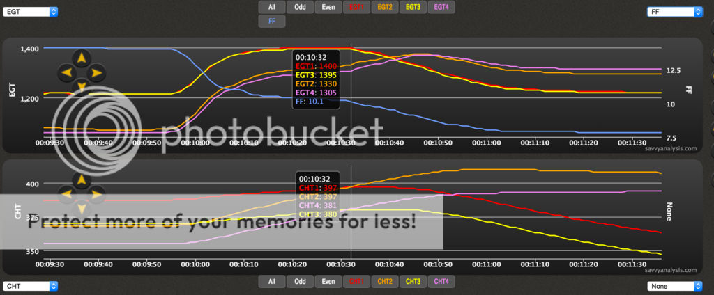
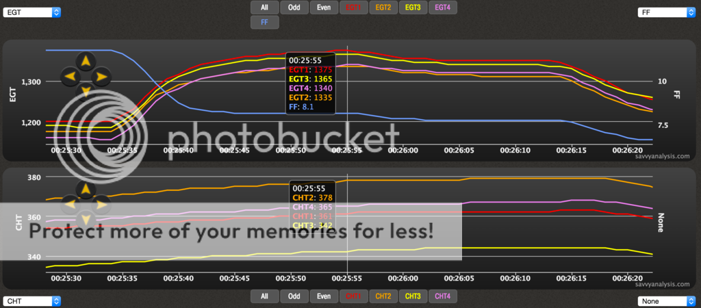
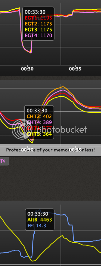
As the pics below show, after 45 seconds of tuning, I went from a GAMI spread of 1.3 to a GAMI spread of 0. Engine runs smooth all the way to about 200 deg LOP where as before I could only get to about 80 deg LOP since before when 80 LOP, cylinders 1/3 were at about 200 deg LOP.

Another benefit is now I have a clear picture of which cylinders I need to focus on for better cooling. Before I would have thought it was 1/3, but actually I need to work on 2/4 first.

Plus, now I am getting more average power with less wasted fuel since all of the cylinders are making optimum power.

Amazing work by the SDS team and Rusty Crawford. This has been many years in the making! I feel so lucky to have gotten to try this out for them!!!

Picture 1 - Leaning to LOP before the tuning - GAMI approx 1.3, notice large EGT spread, also notice 1/3 had highest CHT's when ROP, but coldest when LOP
Picture 2 - Leaning to LOP after the tuning - GAMI 0, notice how 2/4 always have hottest CHT's now.
Picture 3 - ROP climb before tuning - Large EGT spread
Picture 4 - ROP climb after tuning

Picture 1
Before%20Tuning.png


Picture 2
After%20Tuning_1.png


Picture 3
ROP%20climb%20before.png


Picture 4
ROP%20Climb%20After.png
 
Since the lack of plenum volume on the updraft sumps seems to be one of the issues, I wonder if instead of the typically seen 90 degree elbow adapter used to convert to a forward facing servo, if you could instead construct a large volume airbox and attach the servo to the front of that? Im thinking a 10 inch diameter, x 3 inch deep cylinder with a servo mount right in front - essentially a very large volume "elbow". Clearly, it would be a partial solution (if it worked at all), but it would be pretty easy to do.
 
Since the lack of plenum volume on the updraft sumps seems to be one of the issues, I wonder if instead of the typically seen 90 degree elbow adapter used to convert to a forward facing servo, if you could instead construct a large volume airbox and attach the servo to the front of that? Im thinking a 10 inch diameter, x 3 inch deep cylinder with a servo mount right in front - essentially a very large volume "elbow". Clearly, it would be a partial solution (if it worked at all), but it would be pretty easy to do.

Would you design the system with a filter after the servo?
 
Since the lack of plenum volume on the updraft sumps seems to be one of the issues, I wonder if instead of the typically seen 90 degree elbow adapter used to convert to a forward facing servo, if you could instead construct a large volume airbox and attach the servo to the front of that? Im thinking a 10 inch diameter, x 3 inch deep cylinder with a servo mount right in front - essentially a very large volume "elbow". Clearly, it would be a partial solution (if it worked at all), but it would be pretty easy to do.

Interesting idea, but I don't think that would do anything to balance uneven airflow. It may increase the airflow overall, but the imbalance would still be there. By tuning the injectors, the imbalance is a moot point now.
 
An aside...although we may believe the sump to be the root of all evil, until somebody actually puts a sump assembly on a flow bench and measures all four runners, nobody really knows.

It could just as easily be four very different intake ports and valve seats, for example. Some custom shops flow bench cylinders and correct the asthmatic, others don't. Bring the low-flow cylinders up to the level of the best, and the result is more power.

Break.

The ROP reduction in fuel burn is an interesting benefit. The ROP comparison shown here was taken at two different altitudes (and apparently on two different days), but they're close. If both setups were referenced to the same ROP value (say 100 ROP for the leanest cylinder, for example), balance means the richest cylinders are no longer running a lot richer than 100 ROP. I point this out because folks often think of GAMI spread as a LOP tool, but it extends to best power mixtures too.
 
The ROP reduction in fuel burn is an interesting benefit. The ROP comparison shown here was taken at two different altitudes (and apparently on two different days), but they're close. If both setups were referenced to the same ROP value (say 100 ROP for the leanest cylinder, for example), balance means the richest cylinders are no longer running a lot richer than 100 ROP. I point this out because folks often think of GAMI spread as a LOP tool, but it extends to best power mixtures too.

Exactly. Cylinders 2/4 were significantly trimmed leaner which results in more economy when running ROP. This technology results in the engine running better, but also better fuel economy running ROP and LOP. It will take me a few more flights to get an idea of just how much more economical it is now.
 
An aside...although we may believe the sump to be the root of all evil, until somebody actually puts a sump assembly on a flow bench and measures all four runners, nobody really knows.

It could just as easily be four very different intake ports and valve seats, for example. Some custom shops flow bench cylinders and correct the asthmatic, others don't. Bring the low-flow cylinders up to the level of the best, and the result is more power....


The flow bench would certainly give plenty of info, but it still wont tell the tale concerning the interaction between all the cylinders in a dynamic state. And if we think back to the gearhead days when all cars had carbs, plenum volume was a major discriminator in how they performed. Big plenums used to be reserved for big inch, big RPM race engines - but that was with a "wet" flow. With the advent of EFI and "dry" intakes the plenum volumes went way up. Look at the plenum volume of the 200 and 300 HP Lycomings compared to the 180 and 260 versions.

The updraft sump may not be the root of ALL evil, but I suspect that it at least has a bad disposition.
 
Would you design the system with a filter after the servo?

I'm thinking that the servo would remain in the exact same location in space, so the existing filter and inlet would be retained. Not a practical solution for many airplanes, but it will allow for a fairly easy addition to my Rocket - just to test the theory.
 
Actually Ross's new system is a complete engine flow bench. Assuming (I hate that word) the exhaust system is reasonably well balanced, the individual injector adjustments are the airflow imbalance.

With a healthy engine, which it appears he has, to get equal EGT's you have equal AFR's. I know the fuel injectors are usually very close from experience getting a set cleaned and calibrated.
 
An aside...although we may believe the sump to be the root of all evil, until somebody actually puts a sump assembly on a flow bench and measures all four runners, nobody really knows.

It could just as easily be four very different intake ports and valve seats, for example. Some custom shops flow bench cylinders and correct the asthmatic, others don't. Bring the low-flow cylinders up to the level of the best, and the result is more power.

Break.

The ROP reduction in fuel burn is an interesting benefit. The ROP comparison shown here was taken at two different altitudes (and apparently on two different days), but they're close. If both setups were referenced to the same ROP value (say 100 ROP for the leanest cylinder, for example), balance means the richest cylinders are no longer running a lot richer than 100 ROP. I point this out because folks often think of GAMI spread as a LOP tool, but it extends to best power mixtures too.

A flow bench may tell you nothing of the operational dynamics on the engine. It could point you in another useful direction though. Cylinder head / plenum flow is not constant state and as Don already mentioned, exhaust can have a huge effect on intake flow and scavenging. We won't be sure about the cause of all this without peeling back some more layers through testing and elimination, one variable at a time.

Dave Anders will have a SD plenum on his with flow benched heads and equal length exhaust. If that one shows very close spreads, we'll know we're on to something about balanced airflow.

For many years, some of the top engine builders in the auto race world have used pulsed and wet flow benches to more accurately understand what really goes on inside an engine. Not sure what top race shops like Sky Dynamics and Lycon use in the Lyconental world though. You can learn a lot on a flow bench and carry that forward to final validation of your theories and mods on the dyno. When I was building race engines, I built one of each from scratch and spent a lot of time testing and testing. My level of understanding massively increased within a couple of years of having those tools readily at hand in my own shop.

One point which Dan has stressed several times in the past is that EGTs may not be the same even in an engine with well balanced heads, induction and exhaust components but should PEAK near simultaneously, indicating they are at the same AFR under those conditions of rpm and throttle angle/MP. We can see this in Clark's data here even with a 0 GAMI spread.

I want to thank Clark and Rusty for getting these test flights in so quickly and gathering and posting this data. Most interesting and it validates our work in the lab.
 
Last edited:
Speaking about intake manifold designs, I posted the photo of the stock 540 vertical sump earlier to show the very small plenum volume and vastly different intake runner angles and lengths to illustrate a likely poor design with likely unequal flow to each cylinder. It breaks every rule we know in this regard.

dave11_zpsybkbdgzf.jpg


Here's some photos, courtesy of Dave Anders, of his EFI install on his RV4 with the Sky Dynamics induction. Note large plenum volume, equal entry angles, tapered runners, with bell-like transitions and near equal lengths. This is best practice from the performance/ racing world. And I'd expect this to work better than the stock Lycoming vertical sump. Time will tell.

dave17_zps4kjvz0qz.jpg
 
Last edited:
Dog's Breakfast

This is a very poor intake manifold. Off 320 Lycoming I believe. Compare to the SD one above.

badsump_zpsb9tj2kt8.jpg
 
Assuming your 1.5 is 1.5gph difference between first and last peak. If this is the case, fix this first. this will pull the engine cylinders into a closer tolerance in everything.

I just finished this with the assistance of a few friends and ended up with a 0.2 gph spread on my IO-540. It may even be smaller, but it's darn near impossible to move a throttle quadrant in 0.2 gph increments.

G3i EI On 2300 RPM Map 22.7 7500 ft

Size 0.025 0.0255 0.0245 0.0245 0.025 0.025
F/F Cyl 1 Cyl 2 Cyl 3 Cyl 4 Cyl 5 Cyl 6
12.8 1368 1409 1401 1422 1473 1442
12.6 1371 1409 1401 1415 1469 1446

In emails with Don, he shared that this resulted in 1.3% total spread in airflow between cylinders.

I might add a shameless plug for Don's upcoming FI 101 class in March. http://www.vansairforce.com/community/showthread.php?t=134194

Good numbers. What sump are you using?
 
Back
Top