Some insight into things learned on teardown and inspection on our Sube powered 6A. http://www.sdsefi.com/rv16.htm

Van's Air Force
You are using an out of date browser. It may not display this or other websites correctly.
You should upgrade or use an alternative browser.
You should upgrade or use an alternative browser.
Experience with Subaru at 358 Hours
- Thread starter rv6ejguy
- Start date

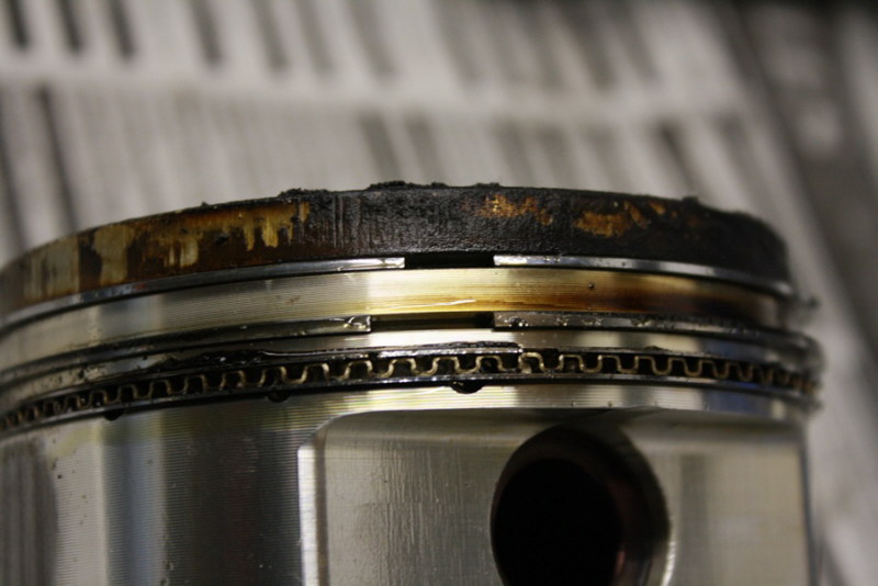
No, ring gaps were not lined up like this, I positioned them this way to show how the upper ring was relaxed in relation to the 2nd ring which had the same free gap as new rings.
I really did not see anything significant to cause this level of oil consumption. I was looking for something obvious. A bit of a mystery and I don't like mysteries...
When the engine was built and for the first 200 hours or so, the engine used essentially no oil- less than a 1/2 quart in 35 hours when I would change it.
Russ---are the cylinders tapered, with more skirt clearance near top?
Tom
Tom
Russ---are the cylinders tapered, with more skirt clearance near top?
Tom
With liquid cooled engine we don't do that as there is little difference in cylinder dimension on a warm engine unlike an air cooled one. There is taper built into the pistons as there is a fair temperature gradient top to bottom there.
The wear you see on only one skirt only is due to these forged pistons not having the wrist pin offset like the OEM pistons.
Overhaul
I get the biggest kick out of tearing down an engine - so thanks for sharing!
Apparently no observable wear on cam or followers?
Put the old valve springs in?
I would bet the cyls are glazed. I have no idea of the phyiscs for that happening on a broke in, water cooled engine but I have had a couple of air cooled that had the exact same symptoms. Essentially no measurable wear on piston or cyls, rings that had lost temper, (obviously wirey instead of brittle), lots of blowby, oil that turned black more quickly that it should and high oil consumption. I can convince myself your cyls look just a little yellow.
rocketbob
Well Known Member
Looks to me like the hone on the cylinders wasn't done very well. The angles look way too shallow. You might want to talk to your ring manufacturer and see what Ra (avg) Rpk (peak roughness) and Rvk (valley roughness) numbers to shoot for on the hone and check with a profilometer.
And are those push on fittings for the oil cooler??
And are those push on fittings for the oil cooler??
I get the biggest kick out of tearing down an engine - so thanks for sharing!
Apparently no observable wear on cam or followers?
Put the old valve springs in?
I would bet the cyls are glazed. I have no idea of the phyiscs for that happening on a broke in, water cooled engine but I have had a couple of air cooled that had the exact same symptoms. Essentially no measurable wear on piston or cyls, rings that had lost temper, (obviously wirey instead of brittle), lots of blowby, oil that turned black more quickly that it should and high oil consumption. I can convince myself your cyls look just a little yellow.
Valvetrain was all mint except replaced all the valves because they had been reground once and did not have enough margin to do again. Did this engine the same way I built 200+ race and performance engines as far as pistons, rings, hone grit. Never had a glazed cylinder yet or an oil consumption problem on any of them, ring faces looked normal, everything looks normal. Yellow tinge is W/B on camera setting and incandescent lighting I think.
Looks to me like the hone on the cylinders wasn't done very well. The angles look way too shallow. You might want to talk to your ring manufacturer and see what Ra (avg) Rpk (peak roughness) and Rvk (valley roughness) numbers to shoot for on the hone and check with a profilometer.
And are those push on fittings for the oil cooler??
I have a recipe for cylinder finish and ring types that has worked flawlessly for 35 years. This one had the same treatment, 220 grit honed on a CK-10. Checked with bore gauge and final miked in 3 spots on each bore. This is a typical CK-10 pattern, very normal in the automotive world.
Barb fittings, Hey it's a car engine!
") - yep, again never had one leak, fail or fracture in 35 years and a lot of race cars. OEMs use them on EFI fuel lines, trillions of hours, very reliable. Just a PITA when you have to take them off, have to cut the hose because you can't pull them off once the clamp is removed, but after 9 years, I want to replace them anyway. Now, I have seen braided stuff and AN elbows break on race cars. Vibration, heavy, stiff braided hose, aluminum elbows, sometimes not a good combination.
- yep, again never had one leak, fail or fracture in 35 years and a lot of race cars. OEMs use them on EFI fuel lines, trillions of hours, very reliable. Just a PITA when you have to take them off, have to cut the hose because you can't pull them off once the clamp is removed, but after 9 years, I want to replace them anyway. Now, I have seen braided stuff and AN elbows break on race cars. Vibration, heavy, stiff braided hose, aluminum elbows, sometimes not a good combination.When you think about the unusual rod bearing damage, consider how hard the crank is oscillating those rod throws during your 1100 to 1600 RPM resonant period.
The bearing damage would appear to be classic (but rare) cavitation damage. The other 2 bearings were so mint, they could have been reused. The flake from the big pit was still inside the pit when I split the rod caps, polished from rubbing around in the hole. I have built and torn down a lot of engines in my time but never seen this before. The mechanism is apparently bubbles in the oil are collapsed by firing pressure, this only occurs on the top shells and usually within the TDC to the 20 degrees after location.
Why only on 2 bearings and what really precipitates it? Could be something like you mention. Diesel engines sometimes have severe cavitation damage to the cylinder liners because of the hard shock of the firing impulses...
I ran Aeroshell in the engine for about 40 hours just for the heck of it, the rest of the time it had 5 or 15W50 Mobil 1. Oil pressure is always 70 psi except hot idle, have around 45. Never starved or run low on oil and no aerobatics.
I need to get another 350 hours on the rebuild to see what it looks like inside next time!
BillL
Well Known Member
Thanks for sharing
+1 on bore polishing for your oil consumption increase. Heavy duty engines, will have an increase in top land deposits and with the temps and piston motion can polish the bores. It looks like it is mostly on the thrust sides of the bore.
Also, the higher temps for the top ring when running at a high load steady state (i.e. cruise) the ring gap may need to be increased. Suggest checking the gap for butting evidence under high magnification.
Was the rod bearing cavitation on all rods? Have you considered all aluminum bearings? They have much higher fatigue resistance than overlaid bearings, but require a very clean oil during early life, and after oil changes. Also, a one factor for cavitation is aeration of the lube oil. Is there any particular churning of the oil that may be occurring? Like crank dipping during climbs etc? You know the engine best.
Just some thoughts from my database.
Thanks for sharing your results in such detail, this could really help make some key modifications to make an non-traditional engine last longer.
The bearing damage would appear to be classic (but rare) cavitation damage. The other 2 bearings were so mint, they could have been reused.
So which ones were damaged? Close to the flywheel or most distant?
+1 on bore polishing for your oil consumption increase. Heavy duty engines, will have an increase in top land deposits and with the temps and piston motion can polish the bores. It looks like it is mostly on the thrust sides of the bore.
Also, the higher temps for the top ring when running at a high load steady state (i.e. cruise) the ring gap may need to be increased. Suggest checking the gap for butting evidence under high magnification.
Was the rod bearing cavitation on all rods? Have you considered all aluminum bearings? They have much higher fatigue resistance than overlaid bearings, but require a very clean oil during early life, and after oil changes. Also, a one factor for cavitation is aeration of the lube oil. Is there any particular churning of the oil that may be occurring? Like crank dipping during climbs etc? You know the engine best.
Just some thoughts from my database.
Thanks for sharing your results in such detail, this could really help make some key modifications to make an non-traditional engine last longer.
Glad it is interesting!
Subaru actually specifies a smaller top ring gap on the turbo EJ22 than the atmo version in an attempt to reduce blowby I'd guess. I ran a few thou more than they recommended because it was less than what I'd normally run in a turbocharged race engine. I will look for ring butting, never checked that. But never butted rings using standard .004 end gap per inch of bore, even on engines producing pretty sustained 225hp/L
Obviously this little 2.2L is working hard to do this job. The life is different from a road race engine where we might extract well over 400hp from it but only for 50-75 hours before teardown. I do have a daily driver shop Nissan 240SX (KA24) which has been turbocharged for the last 15 years and I beat it hard on the street and track, has about 3500 hours on it now and basically no oil consumption. Nothing special inside, built the same way as the Subaru but no forged pistons. Cruise at 3500 rpm on the highway usually and it's under boost... often
I've built many similar turbo street engines. Two friends drove their Toyota turbos for 10 years and 14 years respectively, never used oil, compression still fine after many thousands of hours of collective abuse, bottom ends never touched. But even these do not sustain the high gas loads and upper ring temps as the aircraft application where the peak loading is a lot lower but duration is a lot longer. I would add, that this engine has factory oil jets to cool the bottom of the piston crowns.
No, as I said, only 2 rod bearings had this damage, the other 2 were mint. The OE bearings are an aluminum 2 layer type similar in composition to a GM Morraine 400 type. I used these on many really high output race engines and never saw a problem but there seems to be no sense in putting the same thing back in the 2nd time around. Something is causing this but I would have expected damage to all top shells if the oil was aerated when reaching the bearings. This engine has a windage tray stock, also has about a 30cc reserve pocket in the oil pump discharge housing. The crank is far below the oil level even in the climb attitude. It is possible under really high alpha, the rear counterweights could dip into the oil. The sump and pickup are very deep on this engine, turbo oil was returned far away from the pickup to the left valve cover (this has blown up a few engines due to highly aerated turbo oil being sucked into into the oil pump).
I'd be happy if my non-traditional engine lasted as long as a traditional one...
You make some good points, I'll keep pondering.
Last edited:
So which ones were damaged? Close to the flywheel or most distant?
Have to check my notes on that Dan. You could be on to something. Always appreciate your insights and thoughts!
As a further note on bore finish, when using moly faced rings in Corvair and Toyota engines, I'd specify a 400 grit finish which looks like a mirror almost. No problems with break in, life or oil consumption but the bores had to be really straight and round. Cross hatched from 25 to 45 degrees seemed to make no difference in break in time or life of the rings.
With chrome rings, used on most of my turbo engines, I use 180 to 220 grit stones. I break in engines hard, WOT, boost and 3000-5000 rpm about 30 times, on/off to shear the proud metal and then remove the gas loading to release the particles past the rings. Again, did this with every engine I built and no issues. This Subaru also had very low oil consumption for the first 200 hours and then it slowly started to progressively creep upwards along with the stain on the belly. For the first 200 hours, the belly was totally dry.
I expected the years of automotive engine experience to directly transfer in this case to another application with similar, predictable and successful results. However, I have learned at various times working with aircraft that there is always more and new things to learn and you are never as smart as you might think you are. I must say, the whole process of building the RV, designing and building the FF stuff and systems has been very rewarding and educational. Keeps life interesting and the noggin working. It's my flying laboratory.
With chrome rings, used on most of my turbo engines, I use 180 to 220 grit stones. I break in engines hard, WOT, boost and 3000-5000 rpm about 30 times, on/off to shear the proud metal and then remove the gas loading to release the particles past the rings. Again, did this with every engine I built and no issues. This Subaru also had very low oil consumption for the first 200 hours and then it slowly started to progressively creep upwards along with the stain on the belly. For the first 200 hours, the belly was totally dry.
I expected the years of automotive engine experience to directly transfer in this case to another application with similar, predictable and successful results. However, I have learned at various times working with aircraft that there is always more and new things to learn and you are never as smart as you might think you are.
I must say, the whole process of building the RV, designing and building the FF stuff and systems has been very rewarding and educational. Keeps life interesting and the noggin working. It's my flying laboratory.
Last edited:
Overhaul
Did you happen to check the rig temper relative to new? I know it is hard too waste a set but it could be enlightening. If temper is gone, pretty clear that they get too hot in continuous high output ops. Maybe a different material would solve it or just do routine maintenance. Gaskets, rings and a hone every half a decade ain't so bad so long as it's predictable and non catastrophic.
Ceramic coatings on the piston tops might cut down on heat flux. Especially with unleaded fuel quick will leave fewer insulating deposits.
BillL
Well Known Member
Is this representative?
Here is a 1989 paper on the 2.0, is it representative of the lube system?
http://www.surrealmirage.com/subaru/files/SAE_boxer.pdf
If so, are the cavitated rod bearings in #2-3 or #1-4 perhaps? #2-3 are fed from the center main bearing and #1-4 are fed from one main each. Cavitation typically occurs at a point on the bearing where the pressure drops following the combustion pressure point. A radial force diagram for the bearing relative to the rod would be the typical method of investigation. Most engines in the field never see this (cavitation) as it is cured in the development process.
Sooo, if it is on #2-3 rods, it could be improved with a combination of higher oil pressure, (relief valve spring) , stronger bearing material, or reducing aeration of the oil. The last would be the most difficult. Attention to oil passages may help too. You probably have already thought of these.
One last comment, racing engines, although high power density seldom run very long at peak power; turns, shifting etc affect their ability to reach peak stabilized temps, like juggling a hot potato and surface temps on ones hand. Even F1 are only about 50% load factor per lap. Oval tracks (Indy cars) are a different matter.
Good luck, really interesting stuff.
Did you happen to check the rig temper relative to new? I know it is hard too waste a set but it could be enlightening. If temper is gone, pretty clear that they get too hot in continuous high output ops. Maybe a different material would solve it or just do routine maintenance. Gaskets, rings and a hone every half a decade ain't so bad so long as it's predictable and non catastrophic.
Ceramic coatings on the piston tops might cut down on heat flux. Especially with unleaded fuel quick will leave fewer insulating deposits.
The rings have obviously relaxed as you can see in the photo so this would seem to be the best reason for the oil consumption but I have seen engines with really soft rings, worn out ring lands and huge end gaps with 5 thou of bore wear and they didn't burn this much oil...
The top rings on this engine are taking a licking from the fires of **** above for sure.For the cost vs. hours flown, I can't complain, this is cheap flying and like you say, as long as it is a slow decline without a catastrophic failure, this is tolerable.
Never had good luck with ceramics staying on pistons and once you get combustion deposits over them, I wonder how well they perform? The oil jets would keep these pistons much cooler than an engine without them, this is standard fair for most Japanese turbo engines. I noticed that the bottom of the piston crowns had fried Mobil 1 varnish on them and Mobil 1 cokes at something over 500F.
Some people have PM'd about cost to overhaul and parts replaced:
Replaced:
Rings, rod bearings, valves, head bolts (one time use) cam belt, belt tensioner (nitrogen charged), valve stem seals, gaskets, seals etc.
No measurable wear on main bearings, crank, pins, rod bushings, cams, rockers, valve stems, guides, oil pump, HLAs, cam belt idler bearings, water pump so all of these were reused.
Cost of all the parts was about $1000, $300 of that for the OEM gasket set which is primarily head gaskets, neoprene VC gaskets, stem seals, shaft seals and a bunch of O rings. RTV is used on most other places. Most parts OEM because I trust their quality best.
So the overhaul reserve is less than $3/hr. (my free labor). I am guessing that part is competitive with a Lycoming that goes to TBO with no work and needs average freshening. The big saving was the initial cost of only about $9500 FF (including prop). So I had a lot of money in investments at 10% for the last 9 years (about $35K) compared to the Lycoming/ Hartzell route. The economics work if you don't count the 400 extra hours of build time to do the conversion and 200 hours of debugging and doing stuff over again.
Personally I think mirror finish is a mistake, with the finish too smooth there is no oil retention.
One would think except the engine works fine for a very long time of hard use with almost zero oil consumption. In fact, most moly ring manufacturers recommend a minimum of 320 grit wall finish. Moly rings don't require as much lubrication as other ring types also. The 14 year Toyota 20R turbo engine had Corvair TRW forged pistons fitted with moly rings. Went through 3 friends owning it and maybe 5000 hours. At the end, was using 1/2 quart in about 5000km. Not bad.
Here is a 1989 paper on the 2.0, is it representative of the lube system?
http://www.surrealmirage.com/subaru/files/SAE_boxer.pdf
If so, are the cavitated rod bearings in #2-3 or #1-4 perhaps? #2-3 are fed from the center main bearing and #1-4 are fed from one main each. Cavitation typically occurs at a point on the bearing where the pressure drops following the combustion pressure point. A radial force diagram for the bearing relative to the rod would be the typical method of investigation. Most engines in the field never see this (cavitation) as it is cured in the development process.
Sooo, if it is on #2-3 rods, it could be improved with a combination of higher oil pressure, (relief valve spring) , stronger bearing material, or reducing aeration of the oil. The last would be the most difficult. Attention to oil passages may help too. You probably have already thought of these.
One last comment, racing engines, although high power density seldom run very long at peak power; turns, shifting etc affect their ability to reach peak stabilized temps, like juggling a hot potato and surface temps on ones hand. Even F1 are only about 50% load factor per lap. Oval tracks (Indy cars) are a different matter.
Good luck, really interesting stuff.
Yes, this paper describes the design and testing of the EJ20/ 22 type engines by the Fuji engineers.
It is known on many Japanese designs that the center main often feeds two rod bearings but this has never been an issue in my experience with oiling issues or bearing problems, even at 8500 rpm and 225hp/L and with up to .003 clearance to improve flow rates and bearing cooling. The 71 psi the Subaru operates at has a wide margin at these shaft surface speeds (4500 rpm max). Oil temps in cruise run about 90-95C, max in climb ever was 110C on a hot day going to 12,000 feet.
I will check my notes at the shop tomorrow and be sure which bearings were bad. I elected to try the tougher ACT bearings many builders are using on the 500-1000hp Subaru engines. I believe I'll also switch to 10W30 oil as this is what is specified. The Subaru runs only about .0015 rod bearing clearances. Possibly the heavy oil was a bad choice although the engine has an oil thermostat and I never commenced the runup until we saw 60C OT.
As you can see from the SAE paper, the Fuji engineers go to great lengths to address every problem. Their engines are jewels. I've worked on almost every brand and I really like what they did on the EJ engines. Only a couple small details I'd change. This problem is not something ever reported in auto use or even aviation use by others so I believe it is the application or something I am doing to cause the issue. EJs have accumulated somewhere around 500,000+ flight hours worldwide by my rough estimate in the last 20 years. This isn't something I've ever seen reported nor is it in the most extreme racing conditions.
BillL
Well Known Member
Viscosity
The 10w30 should improve the pressure at the bearing as well (over your 10w60). Good idea, you already are looking at temps too, so that should not be a factor.
That cost story sure balances the total Subbie equation much better that one (me) would think. Thanks for the quantification.
Last comment, i assume you checked for oil leakage from the turbo seals already.
Cheers!
I was hoping this engine would go longer before overhaul as there are lots flying which have gone double or triple this time and one in Oz which was over 3800 hours last time I heard. Mine is one of the high time turbo engines though as far as I know. Anyway I will chalk this up to the learning curve and see how the next stint goes.
Yes, turbo seals fine and actually never give problems on Garretts which are properly treated (15 years on the one in the 240, never touched). All the oil was coming out the breather in this case or going into the chambers.
rocketbob
Well Known Member
One would think except the engine works fine for a very long time of hard use with almost zero oil consumption. In fact, most moly ring manufacturers recommend a minimum of 320 grit wall finish. Moly rings don't require as much lubrication as other ring types also. The 14 year Toyota 20R turbo engine had Corvair TRW forged pistons fitted with moly rings. Went through 3 friends owning it and maybe 5000 hours. At the end, was using 1/2 quart in about 5000km. Not bad.
I've talked to a number of ring manufacturers at the PRI show and they have really come around to specifying the cylinder wall finish in terms of measurable roughness. Not just in terms of average roughness but the roughness of the peaks and valleys. I can rough with a 150 grit diamond hone, for example, come back and hit the bore with a 600 grit stone and the Ra could work out somewhere to 320 but the Rvk and Rpk numbers are going to be way different. Thats why just giving a grit # doesn't really work. Differences in surface hardness are going to affect Rvk and Rpk even though you might be using a 320 grit aluminum oxide stone. Then the stones aren't equal either... 320 grit diamond stones and a 320 grit aluminum oxide stones even though they're equal in grit will result in different finishes.
rocketbob
Well Known Member
Barb fittings, Hey it's a car engine!
I know of an F1 Rocket that was totalled due to a barbed fitting coming apart. If for some reason your oil cooler plugged up the barbed fitting is guaranteed to fail. There are lots of manufacturers now making kevlar hoses that are very light, flexible, and can hold up to 2000psi. Why chance it?
I know of an F1 Rocket that was totalled due to a barbed fitting coming apart. If for some reason your oil cooler plugged up the barbed fitting is guaranteed to fail. There are lots of manufacturers now making kevlar hoses that are very light, flexible, and can hold up to 2000psi. Why chance it?
So how did the barbed fitting come apart? The Aeroquip hose is burst rated to 400 psi, pretty sure the oil filter and cooler will explode way before that happens. Even with the clamp removed, I can put both feet against the bench and pull as hard as I can- over 200 lbs. I am guessing, you can't pull the line off the fitting. This is the last thing I'm worried about. Done right, they simply don't fail.
I've talked to a number of ring manufacturers at the PRI show and they have really come around to specifying the cylinder wall finish in terms of measurable roughness. Not just in terms of average roughness but the roughness of the peaks and valleys. I can rough with a 150 grit diamond hone, for example, come back and hit the bore with a 600 grit stone and the Ra could work out somewhere to 320 but the Rvk and Rpk numbers are going to be way different. Thats why just giving a grit # doesn't really work. Differences in surface hardness are going to affect Rvk and Rpk even though you might be using a 320 grit aluminum oxide stone. Then the stones aren't equal either... 320 grit diamond stones and a 320 grit aluminum oxide stones even though they're equal in grit will result in different finishes.
I'd agree the peaks might matter, valleys no since the ring never touches those, plus after break in most peaks have been sheared off and we settle down to an average roughness anyway. It might affect breakin but I have never had a problem with that. So theory is great but practice trumps theory in my view.
I am mostly working with iron liners and cylinder barrels, most not very hard to medium hardness while some of the liquid cooled blocks have induction hardened bores but are still not Nikasil hard for instance.
Always used aluminum oxide stones.
Sid Lambert
Well Known Member
As you can see from the SAE paper, the Fuji engineers go to great lengths to address every problem. Their engines are jewels. I've worked on almost every brand and I really like what they did on the EJ engines. Only a couple small details I'd change.
I just wish they would widen the frame rails by .5" so the rocker covers and spark plugs were easier to change.
Good luck with these wonderful engines.
Ok, checked the rod bearings this morning and numbers 3 and 4 had the problem so this shoots the theory that both center main fed ones would be the affected ones. Also checked all the top rings for butting, no evidence of that.
3 and 4 are the closest ones to the flywheel Dan.
3 and 4 are the closest ones to the flywheel Dan.
3 and 4 are the closest ones to the flywheel Dan.
I know I asked the question, but after some thought I'm hard pressed to describe the mode shape.
Related or not, it sure would be easy to install a Centaflex while you have the Massive Marcotte off the engine. It should lower the resonant RPM, and hammer with less gusto when passing through it.
rocketbob
Well Known Member
So how did the barbed fitting come apart? The Aeroquip hose is burst rated to 400 psi, pretty sure the oil filter and cooler will explode way before that happens. Even with the clamp removed, I can put both feet against the bench and pull as hard as I can- over 200 lbs. I am guessing, you can't pull the line off the fitting. This is the last thing I'm worried about. Done right, they simply don't fail.
It was an Aeroquip socketless hose and it just blew the hose off.
rocketbob
Well Known Member
valleys no since the ring never touches those
Unless there is enough valley depth the rings push the oil ahead of the rings instead of displacing it in the valleys. Oil getting pushed to the combustion chamber = oil consumption. As you know well here.
I know I asked the question, but after some thought I'm hard pressed to describe the mode shape.
Related or not, it sure would be easy to install a Centaflex while you have the Massive Marcotte off the engine. It should lower the resonant RPM, and hammer with less gusto when passing through it.
This engine has 5 main bearings so I'm thinking some nasty harmonic would have a hard time reaching #3 rod journal but I don't really know anything about that stuff. First I'm trying more flywheel mass as this has worked for a couple others. The flywheel is at the the CNC shop now being machined for 16 steel weights to be fitted near the other edge. This will increase flywheel inertia about 2.5 times. If this doesn't make a big difference, I have taken some measurements and will try fitting a Centaflex next winter during the annual. Taking the drive off is a 30 minute operation or will be with the revised rad/ intercooler setup.
I'll post more photos as work progresses on the rest of the mods.
It was an Aeroquip socketless hose and it just blew the hose off.
I don't use these and wouldn't trust them without a clamp...
Unless there is enough valley depth the rings push the oil ahead of the rings instead of displacing it in the valleys. Oil getting pushed to the combustion chamber = oil consumption. As you know well here.
I am not picturing what you are saying here.
The oil starts out below the piston and the rings are designed to keep it there. The more texture there is in the cylinder wall, the more oil will stay there and not be scraped back down by the rings, like using a rubber squeegee on brushed concrete vs a piece of glass.
skylor
Well Known Member
So how did the barbed fitting come apart? The Aeroquip hose is burst rated to 400 psi, pretty sure the oil filter and cooler will explode way before that happens. Even with the clamp removed, I can put both feet against the bench and pull as hard as I can- over 200 lbs. I am guessing, you can't pull the line off the fitting. This is the last thing I'm worried about. Done right, they simply don't fail.
Beware that there is a significant difference in the way a hose behaves when pressurized internally vs. being pulled. When a hose is pressurized it will expand in diameter, but when it is pulled the hose can actually tighten in diameter slightly. This can mislead you into thinking that it's harder for a hose to come off a barbed fitting than it really is in service.
Every modern car that I've seen has gone away from barbed fittings for high pressure fuel plumbing, and I think for good reason: Reliability. If you look at Formula 1 or Indycar engines, they are all AN plumbing.
Frankly, using barbed fitting for oil and fuel lines in an aircraft is risky, and just plain (plane?) silly! Also the use of brass fittings in a vibration environment is asking for trouble because brass will work harden and can eventually crack.
Skylor
Last edited:
Beware that there is a significant difference in the way a hose behaves when pressurized internally vs. being pulled. When a hose is pressurized it will expand in diameter, but when it is pulled the hose can actually tighten in diameter slightly. This can mislead you into thinking that it's harder for a hose to come off a barbed fitting than it really is in service.
Every modern car that I've seen has gone away from barbed fittings for high pressure fuel plumbing, and I think for good reason: Reliability. If you look at Formula 1 or Indycar engines, they are all AN plumbing.
Frankly, using barbed fitting for oil and fuel lines in an aircraft is risky, and just plain (plane?) silly! Also the use of brass fittings in a vibration environment is asking for trouble because brass will work harden and can eventually crack.
Skylor
Wow, I post a photo of an engine and take a beating here about brass fittings!
I know airplane guys hate barb fittings but to say a brass fitting with 4 barbs on it, using the Aeroquip hose I use and a stainless hose clamp is ever going to come apart at 70 psi is nonsense. I am not exaggerating when I say I've done a good 500-700 of these over the last 35 years in cars and none have come off yet, many have not been touched for over 20 years.
Come on over to my shop and we'll set up a demo for you with 125psi shop air pressurizing a piece of this hose, a brass barb fitting and a stainless worm gear clamp, heat it all up to 200F. I'll bet you $1000 you can't pull it it off.
Of course F1 and Indy car use AN stuff, they are diassembled every race and done right, AN stuff is also very reliable. It would be foolish to use barb fittings on anything taken apart frequently.
Brass fitting on an engine work harden? Come on, you are grasping at straws here. Brass will work harden from repeated deformation but I've never seen brass fittings work harden from vibration, attached to an engine, copper line might ( primer lines on a Lycoming) but even that takes thousands of hours. Let's see, I've got a good 3500 hours and 14+ years on my KA24 turbo with a copper turbo oil feed line and a bunch of brass fittings, never touched them. A KA24 is about as smooth as a paint shaker... I've plumbed dozens of custom turbo systems for the past 3 decades with brass- again never an issue.
All forms of pressure hose assemblies use some sort of mechanical interlock between the hose and fitting and some way to apply radial clamping pressure. The theory is all the same and so is the function.
Many modern cars still use a barbed line and spring clamp or clinched Oettinger type clamp on the EFI hoses. Still a barb underneath and still a clamp.
I bet a few thousands RV guys here also have the Van's supplied Nylon brake fittings and tubing. Not something you find on many certified aircraft but installed and treated properly, it does the job reliably.
Where heat and strength is an issue, I use steel AN fittings and braided line- like on the turbo oil feed on this airplane for instance. I wouldn't use an aluminum AN fitting there actually since one inch away, it is red hot.
My RV10 oil cooler has AN fittings and braided lines as it makes sense there because of the nearby exhaust heat and the lines are short.
Really, there are/ were hundreds of millions of EFI cars built using a single round barb hard line and a spring, worm or wire clamp over a piece of medium pressure rubber hose. They accumulated trillions of hours collectively and they don't fall off otherwise we'd be seeing a lot of car fires when 45 psi fuel sprayed all over hot exhaust parts. VERY reliable otherwise OEMs would have never used them in the first place.
Rotax 912/914 engines use barbed oil cooler fittings, rubber hose, worm clamps and even some brass adapters as well. Works fine, there are many thousands flying worldwide. Are these all death traps? Are people silly to use what Rotax recommends?
Rant over...
Last edited:
rocketbob
Well Known Member
I am not picturing what you are saying here.
The oil starts out below the piston and the rings are designed to keep it there. The more texture there is in the cylinder wall, the more oil will stay there and not be scraped back down by the rings, like using a rubber squeegee on brushed concrete vs a piece of glass.
The rings require a measured amount of oil volume from the cylinder walls. The hone finish does the metering. If the valleys are too deep, the engine will use oil. Too shallow, the engine will use oil. Some ring manufacturers give very specific crosshatch angles, like 40-45 degrees which you should easily be able to get precisely on a CK-10. Too much crosshatch angle, oil consumption will be higher over time. Too little, oil consumption will be higher over time.
You did take the engine apart due to high oil consumption right?
One more thing, the contact area of the valves looks a little wide, and one one of your intake valves looks like the lapped area sits a little too high. Since you're using a Neway seat cutting system there is a guy on ebay that sells blades with all three angles ground into a single set, check it out: http://www.ebay.com/itm/3-angle-val..._Automotive_Tools&vxp=mtr&hash=item19d8084fb3 They work really well.
Last edited:
This engine has 5 main bearings so I'm thinking some nasty harmonic would have a hard time reaching #3 rod journal but I don't really know anything about that stuff.
The "nasty harmonic" is reaching all your rod bearings every time you pass through that big F1 at what, 1450? The crank twists one way, then the other. The question is the amplitude of the angular oscillation at each inertia (the rod throws) along the length of the crank. A "map" of the angular displacements is called a mode shape.
This particular set of mode shapes is an illustration taken from DenHartog's "Mechanical Vibrations". It's for a diesel motor generator set. In the context of this discussion, the key concept is the angular displacements expressed as a decimal percentage of the largest angular displacement, and their distribution along the train of inertias and stiffnesses.
What I've suggested in your case is the possibility of large angular oscillation at #'s 3 and 4. It's not hard to predict the mode shapes (first edition of the above was published in 1934) if you know the inertias and connecting stiffnesses. Unfortunately, we don't in this case so I can't prove anything. I can't even guess, given the long train (belted overhead cams, the vac pump, etc) and the oddities of the urethane bushings as a soft element (they are awful).
First I'm trying more flywheel mass..... If this doesn't make a big difference, I have taken some measurements and will try fitting a Centaflex next winter...
Why half-fix when you can do both now? I'm just sayin'
Last edited:
The rings require a measured amount of oil volume from the cylinder walls. The hone finish does the metering. If the valleys are too deep, the engine will use oil. Too shallow, the engine will use oil. Some ring manufacturers give very specific crosshatch angles, like 40-45 degrees which you should easily be able to get precisely on a CK-10. Too much crosshatch angle, oil consumption will be higher over time. Too little, oil consumption will be higher over time.
You did take the engine apart due to high oil consumption right?
One more thing, the contact area of the valves looks a little wide, and one one of your intake valves looks like the lapped area sits a little too high. Since you're using a Neway seat cutting system there is a guy on ebay that sells blades with all three angles ground into a single set, check it out: http://www.ebay.com/itm/3-angle-val..._Automotive_Tools&vxp=mtr&hash=item19d8084fb3 They work really well.
If your theory is correct, a block honed with an AO 180 grit stone would use oil from day one. Your statement also contradicts your earlier post about fine wall finishes. My KA24 was in fact honed with a 180 grit stone 3500 hours ago and it does not use hardly any oil and the consumption has never changed. Your theory also doesn't hold up on the moly ringed engines I've built honed with 320 and 400 grit stones, again they never used oil, even the one Toyota with 5000 hours on it. Like I said, theory is great until practice shows it is not valid.
The Subaru intake valves have a very narrow undercut face, you have no choice but to plant the contact area about in the middle of the face and stick to the factory specified width of .050. On the exhaust, I stuck to the low end .070 factory spec. You have to remember, these are very small valves so the photo is deceiving. I don't like the 3 way cutters as you are stuck with how they are machined. I did not see suitable ones for this job either.
rocketbob
Well Known Member
A mirror finish and plateau finish are two different things. I like plateau, not mirror. I can show you 4-5 Lycoming chrome cylinders sitting in my shop that have a mirror finish that were using 1qt every 4-5 hours. I have a Sunnen AN-112 portable hone and use N37A45 stones (150 grit), finish with a nylon plateau brush in reverse. Nothing fancy, just works. I have access to a profilometer and with this combination I am able to hone to within recommended roughness specs, partially due to the hardness of a Lycoming cylinder wall.
The "nasty harmonic" is reaching all your rod bearings every time you pass through that big F1 at what, 1450? The crank twists one way, then the other. The question is the amplitude of the angular oscillation at each inertia (the rod throws) along the length of the crank. A "map" of the angular displacements is called a mode shape.
This particular set of mode shapes is an illustration taken from DenHartog's "Mechanical Vibrations". It's for a diesel motor generator set. In the context of this discussion, the key concept is the angular displacements expressed as a decimal percentage of the largest angular displacement, and their distribution along the train of inertias and stiffnesses.
What I've suggested in your case is the possibility of large angular oscillation at #'s 3 and 4. It's not hard to predict the mode shapes (first edition of the above was published in 1934) if you know the inertias and connecting stiffnesses. Unfortunately, we don't in this case so I can't prove anything. I can't even guess, given the long train (belted overhead cams, the vac pump, etc) and the oddities of the urethane bushings as a soft element (they are awful).
Why half-fix when you can do both now? I'm just sayin'

This is very interesting, as always, you bring some thought provoking data Dan. I would not have thought displacement would be so high down the line. I don't know jack about this as I said before which is why I like to see your posts.
In this case, the gearbox is holding up ok. If the gearboxes were breaking up or the bushings were lasting only 50 hours, I'd have to instrument the thing somehow to learn what is actually happening.
The rubber drive bushing are substantially deformed in the direction of engine loading. My gut is telling me, I can reduce these forces before they reach the bushings or Centaflex by having higher flywheel inertia. (but my gut has been wrong before).
Yes, there a few unusual things in the mix here. The reason for trying the increased inertia first is about the scientific method- one change and observe results. Make 2 changes with no pre and post data and you may not learn as much as you are not sure which change made which difference. Also, 2 others with Marcotte boxes have increased flywheel inertia by changing out to steel flywheels, both reported F2 was almost eliminated (gut feeling, no instrumentation). But you don't need instrumentation to tell you it is a bad thing to hold the engine there.
The middle of F2 appears to peak around 1250 rpm, it extends from about 1050 to about 1500 rpm. Interestingly if I am accelerating the prop, it persists to about 1550 and when decelerating the prop, I can get down to about 1400 before it gets bad again. This only occurs during taxi. I push up the power quickly to get over 1500 as soon as possible.
I had wondered why the gearbox was designed with large open windows top and bottom where the flywheel and couplers reside, I figured it was good for inspection. It did not occur to me until you weighed in on the TV discussion a few years back that these rubber bushings had to dissipate a lot of heat at times. If the box was sealed to the engine, these bushings would probably fail in short order.
Your comments also made me curious about angular displacement so I checked this by applying torque to the prop statically a couple years ago. These bushings are very stiff together. If I recall, I had to apply over 350 lb./ ft. to get about 1 degree of bushing deflection. You can see from the pix how much the bushings have deformed and the odd marks in the drive ring bores (still can't figure that out). But with crude calculation from this it would seem that peak loading may easily be in excess of 1000 lb./ft and possibly far above that figure. I want to fit something to measure the actual running deflection at F2. Thinking about a simple way to do that with a deformable pointer or maybe even modeling clay. Wish I would have done this before the flywheel mod though.
Last edited:
If the gearboxes were breaking up or the bushings were lasting only 50 hours, I'd have to instrument the thing somehow to learn what is actually happening.
You have an unexplained rod bearing breakup, apparently unique to your setup.
The reason for trying the increased inertia first is about the scientific method [
I sincerely beg your pardon, but the scientific exploration of torsional issues was 95% done by WWII. You're a smart guy. Quit pumping the pooch and apply the known.
You just had the engine apart. You know about bifillar suspension to determine inertia, but you didn't do it.
With the lump inertia of the crank/flywheel assembly and the lump inertia of the prop/gearbox you could select an off-the-shelf NBR elastomeric torsional coupler with a torsional stiffness and torque capacity listed right next to the part number. You know, an engineered component.
But with crude calculation from this it would seem that peak loading may easily be in excess of 1000 lb./ft and possibly far above that figure.
Yep, thus the noise and shaking airplane. What do you figure a 1000 lb-ft torque oscillation applied to the crank at 45 hertz is doing to the rod throws?
LoopDLoop2
I'm New Here
oil consumption
I must say that is has been a very "spirited" post. All of you have very valid points. I would say from my experience that there is a couple of over looked areas.
First. Whose piston is it? Some manufacture can't cut a flat ring grove to save their live.
Sec. What is the oil ring tension? With aftermarket rings there are many choices.
Third. What is the actual blow by in CFM? There is a meter to measure this.
As far as what "grit" to use. Forget it. Use RPK,RVK,PK and VO numbers based on what the ring is made of. Just remember. Crome won't get you home. There are many other materials that are much better. Total Seal has a ring I use in extreme application that I swore by. C23 is by far the most robust and has a easier time of sealing. Again the numbers are crucial. It has a carbon nitride face. C72 is a titanium nitride face but is a little fussier. How about cross hatch angle. A steep angle always produces more blow by. To flat and the ring will ?skate? across the bore and wear quickly. I found that 26-29 degrees is about right for any application. This is proven with a blow by meter and time in service.
As far as a CK-10, good machine in its day but has issues. Main one is ?loabing? cylinder. Just because the mike says its straight and round doesn?t mean its straight and round. How about a torque plate when you honed it?
I could go on and on with honing. With many years of perfecting it in NHRA Pro Stock competition I can say it is never perfect. I you have any questions and I have not pissed anyone off with my first post I am sure I could help you out.
By the way, cool forum. Looking into a RV8 TD and can?t wait to get my hands on one.
You have an unexplained rod bearing breakup, apparently unique to your setup.
I sincerely beg your pardon, but the scientific exploration of torsional issues was 95% done by WWII. You're a smart guy. Quit pumping the pooch and apply the known.
You just had the engine apart. You know about bifillar suspension to determine inertia, but you didn't do it.
With the lump inertia of the crank/flywheel assembly and the lump inertia of the prop/gearbox you could select an off-the-shelf NBR elastomeric torsional coupler with a torsional stiffness and torque capacity listed right next to the part number. You know, an engineered component.
Yep, thus the noise and shaking airplane. What do you figure a 1000 lb-ft torque oscillation applied to the crank at 45 hertz is doing to the rod throws?
Well, all Subaru aircraft installations with light flywheels seem to have similar F2 frequencies, no matter what drive or prop as I have feedback from dozens of users from Flysoob and Subenews as well as a bunch of users I polled by email. Some have taken the engines apart for other things like holed pistons or bad HGs and nobody has seen cavitation damage so I am not totally convinced yet that this is caused by a TV issue. That being said, I want to learn something and try to reduce TV too. Clearly it it not good for things. The one EJ25 installation which did not have noticeable F1 or F2 periods in the traditional places had a 22 or 24 lb.flywheel and also a lightweight carbon prop.
If you remember about 4 years ago I did do a bifillar suspension test on a scrap 2L crank and sent you the results. I believe you said we'd need to calculate or model the stiffness to fill in the equation. We kind of stopped there. You are right, I could go to the coupler site and probably make a half decent guess at a coupler/ damper choice and that may be my next step. But like dyno testing, you never change cam timing and ignition timing at the same time, you learn nothing that way. I want to see what effect flywheel inertia change has on F1 and F2. If it is not pretty much gone, I swear I'll do this.
Torsional Vibration Analysis
I think it would be very instructive and not very expensive (perhaps around 1 Airplane Financial Unit or 1K) to have a torsional vibration analysis done. In the marine business, either the engine manufacturer or the coupling manufacturer can do this. In the airplane business with alternative engines, it probably comes down to the coupling manufacturer. So why don't you ask Centa (as one supplier for example) to do one for you for your "airboat". First ask if they have any data on the Subaru engine. If not then you will have to measure the prop shaft, gearbox, and crank widths, lengths and inside and outside diameters, and supply them with the weights of the conrods and pistons. The first step is to calculate a mass-elastic diagram of the system from these measurements. Then the mass-elastic system is input into a computer program for analysis. This will show the magnitude of the torsional peaks and shapes. A torsionally soft coupling is then selected and the system remodelled to reduce the peaks and shapes to an acceptable level.
You are right about the flywheel, adding weight (or subtracting) will alter the mass part of the mass-elastic diagram at that location. But this does not guarantee the problems goes away, it may merely shift the magnitude of the torsional peak to a different rpm and move the shape around in the system.
The torsional vibration analysis may or may not give you insight regarding your bearing failures, however, it is a prudent calculation to make with any new engine/gearbox/propeller installation.
Incidentally, although this calculation is common in aircraft (certified) and marine applications, I am not aware of it being done in motor cars or trucks. I suspect that the presence of rubber tires at the end of the driveline, may damp the vibrations sufficiently.
I must say that is has been a very "spirited" post. All of you have very valid points. I would say from my experience that there is a couple of over looked areas.
First. Whose piston is it? Some manufacture can't cut a flat ring grove to save their live.
Sec. What is the oil ring tension? With aftermarket rings there are many choices.
Third. What is the actual blow by in CFM? There is a meter to measure this.
As far as what "grit" to use. Forget it. Use RPK,RVK,PK and VO numbers based on what the ring is made of. Just remember. Crome won't get you home. There are many other materials that are much better. Total Seal has a ring I use in extreme application that I swore by. C23 is by far the most robust and has a easier time of sealing. Again the numbers are crucial. It has a carbon nitride face. C72 is a titanium nitride face but is a little fussier. How about cross hatch angle. A steep angle always produces more blow by. To flat and the ring will ?skate? across the bore and wear quickly. I found that 26-29 degrees is about right for any application. This is proven with a blow by meter and time in service.
As far as a CK-10, good machine in its day but has issues. Main one is ?loabing? cylinder. Just because the mike says its straight and round doesn?t mean its straight and round. How about a torque plate when you honed it?
I could go on and on with honing. With many years of perfecting it in NHRA Pro Stock competition I can say it is never perfect. I you have any questions and I have not pissed anyone off with my first post I am sure I could help you out.
By the way, cool forum. Looking into a RV8 TD and can?t wait to get my hands on one.
Welcome here and I appreciate your interest. The piston is JE as described on the web page. The oil ring tension, well, frankly never paid attention to this as I have never had an oil consumption problem before- tried to duplicate the same same successful recipe I've used to build engines professionally for quite some time. So, the answer is- I have no idea.
I don't own a blowby meter but I could show the the belly of the aircraft- blowy at the end was "severe". But when built originally, the belly was completely dry after 35 hours and stayed that way for over 200 hours.
Chrome got me home for 35 years building turbocharged engines... and was the choice of the Fuji engineers who designed this engine. Perhaps old school but it still works very well in this application.
This was honed at a pretty flat angle which I have found works fine too.
CK10 also dated like me but again, gave good results with a good operator, engines worked fine.
Subaru engines do not use head bolts into the block deck like most other engines. A torque plate would have minimal effect IMO. Of course "round" and "straight" are relative terms and I agree, the rounder and straighter, the better. With old equipment and measuring stuff, I do the best I can.
What is TBO on a Pro Stock engine? Curious. What BMEP at torque peak and power peak?

