What's new
Van's Air Force

Don't miss anything! Register now for full access to the definitive RV support community.

Built a courtesy light for the baggage area

Draker

Well Known Member
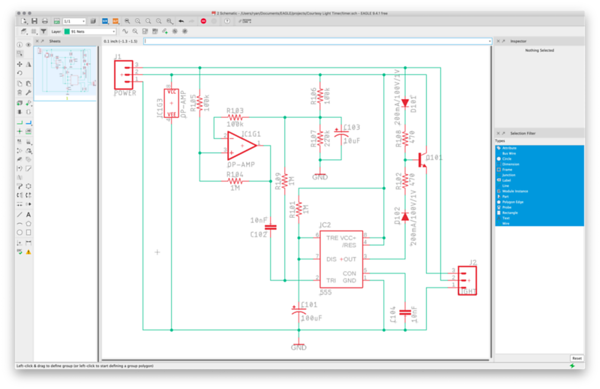
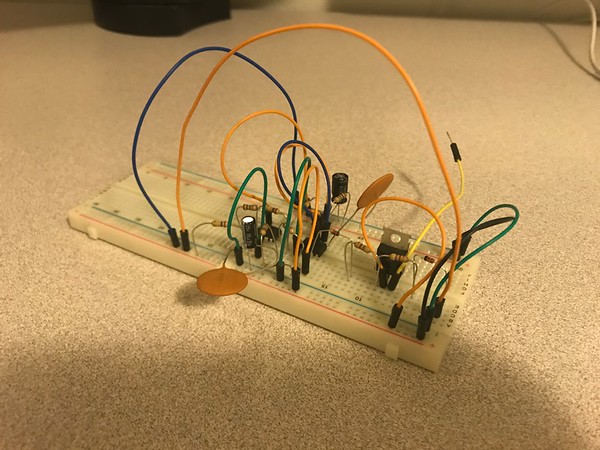
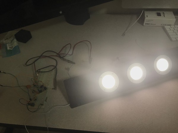
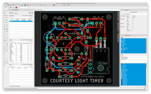
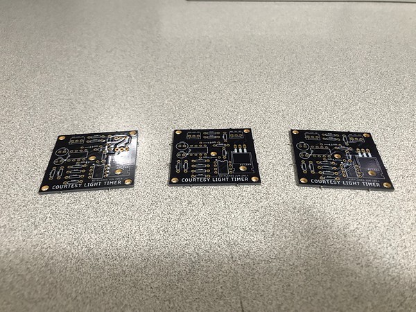
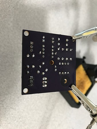
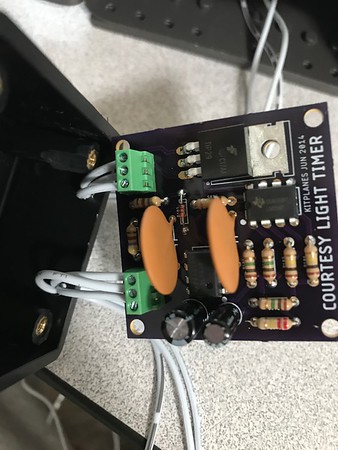
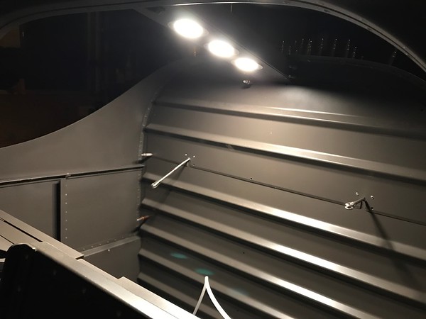
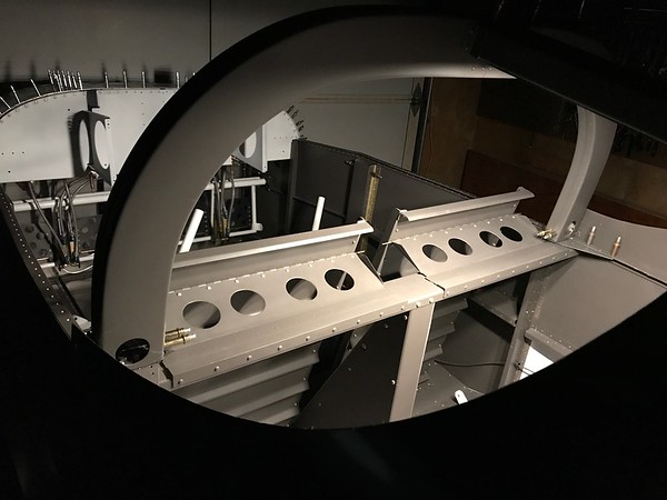
As a fun little side-project while I wait for my finishing kit to arrive, I went and implemented a courtesy light for my RV-7A. The point of this is to briefly provide some light after you turn the master switch off so you can see as you're getting out. Like how your car's internal lights work when you remove your key. I chose to put the light over the baggage area. Here are the steps I followed. This was a pretty easy project but I thought I'd post a write-up because I'm pretty proud of how it turned out. The usual "this is just what I did, your airplane is your airplane" disclaimer obviously applies!

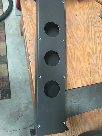
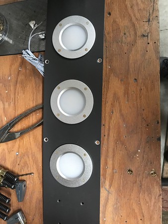
Cut a cover plate to go over F-732A out of 0.025 sheet. Do a search here, many builders seem to be covering this channel up for cosmetic reasons.

Drilled, dimpled, and attached 8 #6 nutplates to F-732A

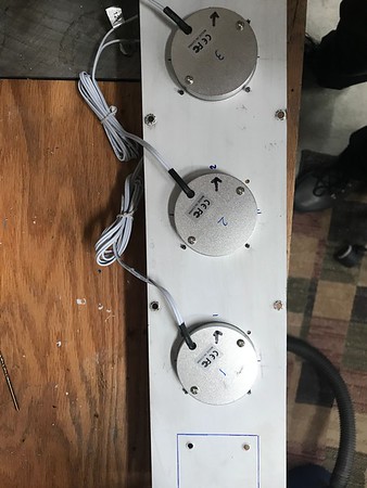
Purchased a pack of 4 LED dome lights from Amazon:

ALOVECO LED RV Boat Ceiling Light 12V LED Recessed Cabinet Lights Waterproof Ultra-Thin LED Interior Lighting for Motorhome Sailboat Yacht 3000K Warm White(4 Pack) (3000K)
https://www.amazon.com/gp/product/B07B8B2XJ7/

Each of these came with a metal mounting bracket on the back. I removed them.

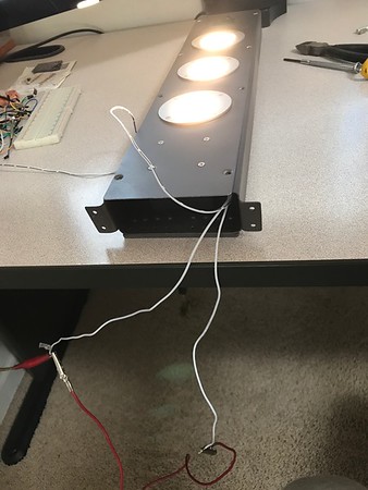
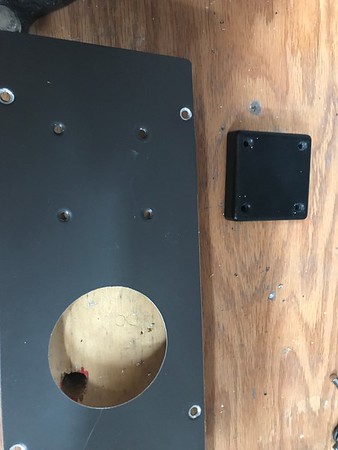
Drilled clearance holes for LED lights (55mm).


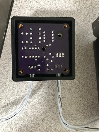
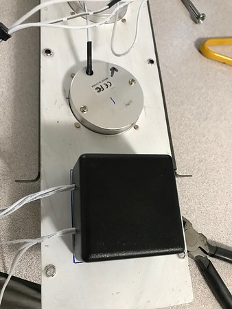
Purchased Hammond 1594A plastic project box. Outer dimensions are 56mm x 56mm x 40mm.

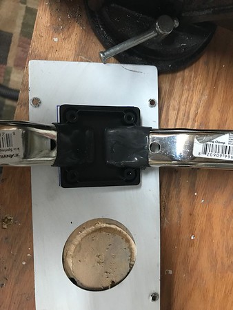
Positioned box lid and clamped in place.


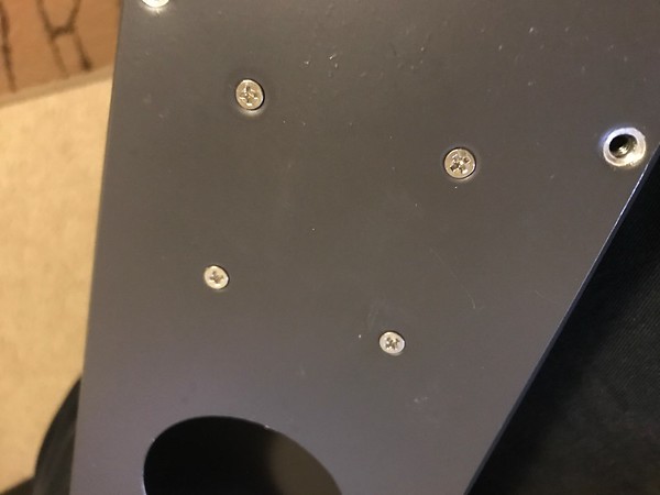
Holes in plastic box are M3. Clearance hole is 3.4mm, #30 is close enough.

Match drilled cover plate through lid.

Dimpled #30.


Screws will not be perfectly flush but again, good enough.


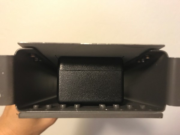
The box itself fits like a glove. It's almost as if it was made for this application!


Drilled #40 attach holes for lights.

Match drilled to cover plate. I could not avoid poor edge distance, due to how thin the lights' flanges are. This is the only part of the project I'm not totally satisfied with.


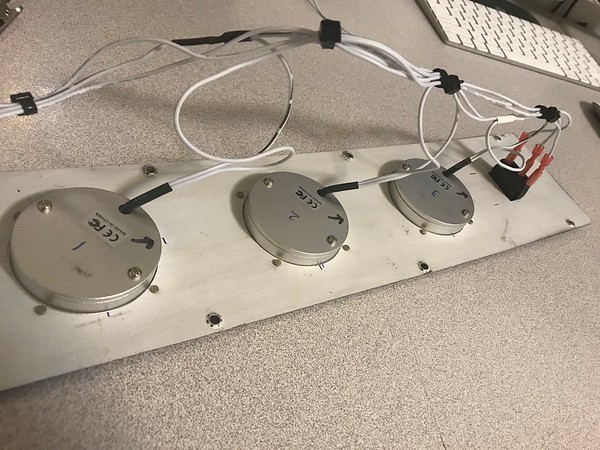
Countersunk light faces for flush rivets.

Riveted lights to cover plate.


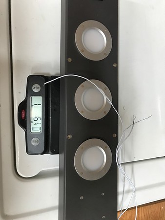
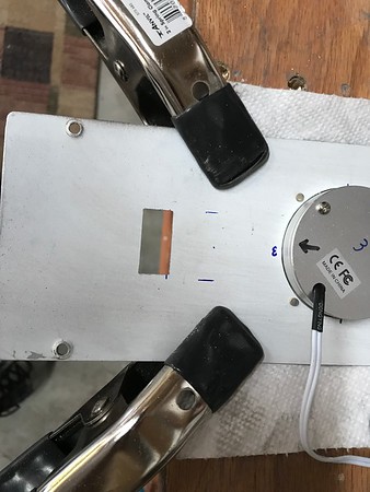
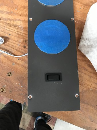
Cut a hole for the function selector switch (approx. 1" x 7/16"). Switch is an on-off-on SPDT rocker switch.
Right = power comes from courtesy timer circuit. Center = off. Left = bypass courtesy timer circuit (light goes on and off with master switch).


Snapped switch into place.


Wired LED lights in parallel, with all + wires connected to center terminal on switch.

Connected two other wires to the other terminals on the switch.

 
Next it was time to start on the timer circuit. I take no credit for the circuit design. This schematic is based entirely on http://www.rstengineering.com/kitplanes/KP2014/KPsch RevB.pdf I just entered it into Eagle.


See Kitplanes July 2014 article by Jim Weir for full information. I did not have a subscription or access to the article when I built this, but the circuit is very basic and composed of:
1. A monostable 555 countdown timer circuit. When pin 2 of the 555 is pulsed low, output will go high. Voltage at pin 6 will slowly increase as C101 charges until it is 2/3 of VCC (~9.1V), at which point output goes low and the capacitor is discharged.
2. An op-amp configured as a non-inverting comparator with hysteresis, which pulses pin 2 low on the 555 when the master bus goes off. The comparator's reference voltage is set by the R106/R107 voltage divider. As designed, the reference voltage is 1/2VCC which I found too low to reliably trigger the timer, so I increased the reference voltage to about 2/3VCC by replacing R107 with a 220k resistor.
3. A bipolar power transistor which energizes the output lighting circuit based on either the master bus being active or the output of the timer.

My mods: Removed inline switch on the master bus. Replaced R107 with 220K resistor to adjust the op-amp's reference voltage. Added 10n capacitor between 555 CON pin and ground to eliminate noise on the internal voltage divider.

J1 (input) terminal:
Pin 1: GND
Pin 2: "Always On" Battery +12V
Pin 3: Master +12V

J2 (output) terminal:
Pin 1: GND
Pin 2: Master bus
Pin 3: Timer output (max 1A)

One drawback of this setup is that the lights must be powered by a separate "always on" bus, and if you want them dimmed, you need to use a dimmer circuit separate from your other cabin lighting. Tested everything out on a breadboard first.


The courtesy timer's output duration is based on the time it takes to charge C101 to 2/3VCC, given by t = ln(3) x R x C. As designed, R=1M, C=0.0001, so t=109.86s. Upon testing the circuit on a breadboard, I found it held the light on for 115 seconds after the master bus went off, very close!


Laid out the circuit board. I chose to go with a two sided board, with ground traces on the bottom layer. All traces are 32mil wide, and the board is sized and holes placed to fit into the hammond 1594A plastic project box. This is a very simple circuit, so laying out the board manually was a breeze. I originally planned to go with molex connectors for input and output wiring, but later decided to use screw-in terminals.


Sent the board file over to https://oshpark.com for PCB fabrication. Got three boards produced for $15.30


Soldered on all components. Note: If you orient all the color lines on the resistors so they line up nicely, your airplane gains 1 knot top speed.


There was interference between J2 and the project box, which I fixed in a subsequent board design.


Assembled the box around the board and attached to the cover plate.


Last edited:
Bench test


Lights draw 0.56A when connected direct to power, 0.18A for 115 seconds after master switch is off.


Entire unit, including screws weighs 22.25oz.


Here's how it looks in the dark after installation in the fuselage:


BOM for circuit board components, switch, and box:

1x Hammond 1594ABK BOX ABS BLACK 2.21"L X 2.21"W
1x Bulgin C1520AABB-B SWITCH ROCKER SPDT 16A 250V
2x OST OSTVN03A150 TERM BLK 3P SIDE ENT 2.54MM PCB (J1, J2)
1x Nichicon UVZ1E101MED CAP ALUM 100UF 20% 25V RADIAL (C101)
1x Nichicon UVZ1E100MDD1TD CAP ALUM 10UF 20% 25V RADIAL (C103)
2x Vishay D103K69Y5PL63L0R CAP CER 10000PF 500V Y5P RADIAL (C102, C104)
2x ON Semiconductor 1N4148 DIODE GEN PURP 100V 200MA DO35 (D101, D102)
1x ON Semiconductor TIP29 TRANS NPN 40V 1A TO-220 (Q101)
1x TI LM358P IC OPAMP GP 2 CIRCUIT 8DIP (IC1)
1x TI SE555P IC OSC SINGLE TIMER 100KHZ 8-DIP (IC2)
3x Stackpole CF14JT1M00 RES 1M OHM 1/4W 5% AXIAL (R101, R104, R109)
2x Stackpole CF14JT470R RES 470 OHM 1/4W 5% AXIAL (R102, R108)
3x Stackpole CF14JT100K RES 100K OHM 1/4W 5% AXIAL (R103, R105, R106)
1x Stackpole CF14JT220K RES 220K OHM 1/4W 5% AXIAL (R107)

LED lights: $30.99
Project box: $9.14
Rocker switch: $5.46
Components (bulk): $4.14
Circuit board fabrication: 3 for $15.30
Total cost per project was $54.83 + shipping and it was a lot of fun.

A few more pictures can be found here: https://stiletto.smugmug.com/RV7/LightingAvionics/
 
Sure, Bill, I've got two extra of the v1 board design, and can send you the Eagle files if you want to play around yourself.
 
Trying to understand the control logic in how this works... So when the switch is in the "always on" mode, the lights go on and off with the master, that makes sense. When it's off, nothing happens. When it's in the "courtesy light" mode, do you just leave the switch there full time, like we do in our cars, and the lights come on when the master is off (until the circuit times out)? Or do you need to turn the switch off manually after the lights go out?

I wonder if a canopy switch would be a good option, like the door switch on a car... Opening the door triggers the lights, which stay on until the timer runs out or you close the door again?
 
Rob, when the switch is in courtesy light mode, the lights will be on with the master switch AND for ~2 minutes after the master switch goes off.

I plan to leave the switch in the center (off) position most of the time. If it's dark out before I exit the plane, I can switch it to courtesy light mode while the master is on, which will turn on the baggage lights. Then, I turn off master, grab everything and leave, and the lights go off by themselves. Next time I get into the plane, I'll set the switch back to the center/off position.

Never thought of using the canopy switch for this. Definitely do-able with a slightly different circuit/wiring.
 
I think you'll find that requiring a switch activation every time will mean you occasionally forget it. Or you'll find you want the light on just slightly longer than the timer allows, so you'l flick the master on to re-charge it and then forget to turn it off... That kind of thing. You'll find that it's not always in the state you want it, when you go to use it, so you'll have to think about it every time rather than it just doing what you expect it to every time.

I like clever circuits like this that make life easier, but I hesitate on circuits that only "seem" to duplicate functionality that we're familiar with (and by default expect to work like it does elsewhere). The three-position switch (always on, off, and controlled-by-door) is completely understood by anyone driving a car, so in my opinion the overhead light should work the same way in the plane. Lift canopy, light comes on, close canopy, light goes off (or stays on for a set delay and then goes off). In any case, not requiring input on a regular basis to set the operational state... It "just works" and doesn't draw any power when the light is off. If you need more light while flying, or need it on for a longer time on the ground, you can reach up and flick it on, just like we do in a car.
 
Looks great!!

Perfect set up for the tip up!!! On the slider I put LED's in the curved supports and under the cross bar. Really lights things up nicely. Also mounted a LED strip across the bottom of the instrument panel. Nice for lighting the floor area. All wired to a Hot Buss with switches on the panel.
 
Rob, great feedback for the next version! I agree something more automatic would be nicer.
 
Back
Top