
Van's Air Force
You are using an out of date browser. It may not display this or other websites correctly.
You should upgrade or use an alternative browser.
You should upgrade or use an alternative browser.
AX-O's Fastback RV-4
- Thread starter AX-O
- Start date

Bob Kuykendall
Well Known Member
The air molecules and I can")
"The air has fingers, not eyes."
You might be surprised how asymetrical some aircraft actually are when you look closely. I've measured Nationals-winning sailplanes with templates that show that the right and left wings look like their airfoils came from two completely different gliders. Yet they go like stink and fly straight as arrows.
Thanks, Bob K.
Flow viz
Axel-
Good timing on this subject. I am finishing up my Phase I and just put my pants and gear fairings on a couple days ago. Per the manual, I aligned the fairings by string method, no weight on gear. Nevertheless, during flight I was definitely getting some roll/yaw forces (although this could have been due also to pant misalignment).
I waited to do the top/bottom intersection fairings, since I figured doing so would preclude me from adjusting the gear fairings based on flight tests. I'm glad I did so. After the first flight with fairings, I decided to do a flow viz experiment. I smeared engine oil along the leading edge of both fairings, then doped it with talcum powder, and went out and flew at cruise speed for an hour. When I returned, I had a very nice visual flow pattern that showed both fairings to be misaligned. Adjusted the fairings (TLAR method), redid the flow viz, and now the flow is straight and roll/yaw forces much reduced (there's not much I can do about wheel pant alignment at this point). I'm hoping the addition of the intersection fairings doesn't mess things back up again!
I'll post pics and a more detailed explanation on a dedicated thread in a couple of weeks when I have a bit more time. In any event, you may want to consider waiting to do the intersection fairings until once you've had a chance to fly the plane.
Eric
smokyray
Well Known Member
Ah, the details...
Excellent subject. I will add however that over time less importance will be spent toward alignment and appearance and more on how to keep them attached and in one piece.
I found in 2000 flying hours on my RV4 and HR2 "life stresses" on them challenged structural integrity (especially on rough turf or gravel) or just the landing gear movement itself. My point? Leave some wiggle room around the base of the fairing (where the leg fairing attaches) and put some MhWh tape around them where movement occurs. Use large area washers on all holes and thread lock as the screws loosen easily. Put Silicon film on the back side of the fairing where it chafes any painted surface.
Even with all of the above they take a beating. Be ready with HySol...
V/R
Smokey
www.iamanet.org
Axel-
Good timing on this subject. I am finishing up my Phase I and just put my pants and gear fairings on a couple days ago. Per the manual, I aligned the fairings by string method, no weight on gear. Nevertheless, during flight I was definitely getting some roll/yaw forces (although this could have been due also to pant misalignment).
I waited to do the top/bottom intersection fairings, since I figured doing so would preclude me from adjusting the gear fairings based on flight tests. I'm glad I did so. After the first flight with fairings, I decided to do a flow viz experiment. I smeared engine oil along the leading edge of both fairings, then doped it with talcum powder, and went out and flew at cruise speed for an hour. When I returned, I had a very nice visual flow pattern that showed both fairings to be misaligned. Adjusted the fairings (TLAR method), redid the flow viz, and now the flow is straight and roll/yaw forces much reduced (there's not much I can do about wheel pant alignment at this point). I'm hoping the addition of the intersection fairings doesn't mess things back up again!
I'll post pics and a more detailed explanation on a dedicated thread in a couple of weeks when I have a bit more time. In any event, you may want to consider waiting to do the intersection fairings until once you've had a chance to fly the plane.
Eric
Excellent subject. I will add however that over time less importance will be spent toward alignment and appearance and more on how to keep them attached and in one piece.
I found in 2000 flying hours on my RV4 and HR2 "life stresses" on them challenged structural integrity (especially on rough turf or gravel) or just the landing gear movement itself. My point? Leave some wiggle room around the base of the fairing (where the leg fairing attaches) and put some MhWh tape around them where movement occurs. Use large area washers on all holes and thread lock as the screws loosen easily. Put Silicon film on the back side of the fairing where it chafes any painted surface.
Even with all of the above they take a beating. Be ready with HySol...
V/R
Smokey
www.iamanet.org
learningtofly
Member
Bulkhead
Would you happen to have the coordinates for your new f-407?
Would you happen to have the coordinates for your new f-407?
Michael White
Well Known Member
Very Nice!
acam37
Well Known Member
Canopy fitting
Maybe someone can help me out on this? I'm in the process of building a canopy frame and fitting the canopy on my fastback -4. The first question is probably for Axel. I noticed in Axels pics of his canopy frame, that he welded the tubing to the inside of the rear square braces. I plan on running the tubing on the outer side. Is there a reason it needed to be on the inside in the back?
The second question is how far forward can the canopy be? Is there a safe maximum distance it can go? This canopy I got from Todd's Canopies has plenty of extra material to go as far forward as I want to go.
AX-O
Well Known Member
Sir,
I can answer both questions. I am assuming you are the gentleman rebuilding the -4 in texas.
1) the tube does not need to go inside. It can go on the outside. I chose to go on the inside because to me it looks better and i would not have to worry about that tube interfering with other things in the cockpit. You cant go behind because the canopy wont close. You cant go outboard because the width of the canopy wont match the airframe. Your only options are forward or inboard of the square tube. Unless you cut something else.
2) you can go as far forward as you wish. I moved mine forward approx 4 inches of the original location (instrument panel). I noticed the the same thing you did.
Hope that helped.
Just a side note before this thread digresses. I am documenting my build. I would request that anyone with questions to contact me directly or post on a separate thread and i can answer. Thanks for everyone's consideration.
Sid Lambert
Well Known Member
A$$ Clown,
I like your call sign!
You don't happen to remember how much you had to trim off the VS to clear the new turtle deck do you?
I like your call sign!
You don't happen to remember how much you had to trim off the VS to clear the new turtle deck do you?
AX-O
Well Known Member
Sid,
I saw your post this morning but could not answer your question. I was going to post some pics but may not be able to.
There are 2 things which will dictate the answer to your question.
The first one and most obvious one is the F410 bulkhead placement. In some -4 (depending on the plans used) that bulkhead is located further forward or aft (not by much). That will impact the angle of the turtle deck and the amount of aluminum skin under nose of the Vertical Stab.
The other not so obvious one is the spacer (or not) used between the Horizontal Stab and the fuse longerons. The original plans called for no spacer. Updated plans call for a 3/16 spacer (I think, don?t have the plans in front of me).
In my particular combination, I cut very little off the Vert Stab?s nose. I did not have to make any changes to the nose rib or re-rivet the nose like on the plans for the RV-8 Show Planes fastback conversion.
I have heard people cutting a hole on the turtle deck skin to allow the Vert Stab to sit inside the hole. I personally would not go that route. The small radius made by the F410 bulkhead gives a lot of strength to that area of the fuse.
My advice would be to wait until you have the turtle deck and the Horizontal Stab in place, then take your time to cut the least amount possible off the nose rib. I hope that answers your question. Sorry for the extra info, but most likely it will also help someone else.
Sid Lambert
Well Known Member
Axel,
That is a perfect answer, thank you. I'm rebuilding the tail group this winter but probably won't do the turtle deck until next winter.
I will just bias that nose rib about a half inch up and leave the vs skin alone until I do the turtle deck work.
Your airplane is looking awesome.
That is a perfect answer, thank you. I'm rebuilding the tail group this winter but probably won't do the turtle deck until next winter.
I will just bias that nose rib about a half inch up and leave the vs skin alone until I do the turtle deck work.
Your airplane is looking awesome.
AX-O
Well Known Member
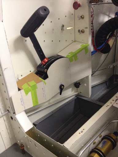
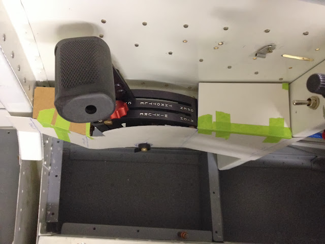
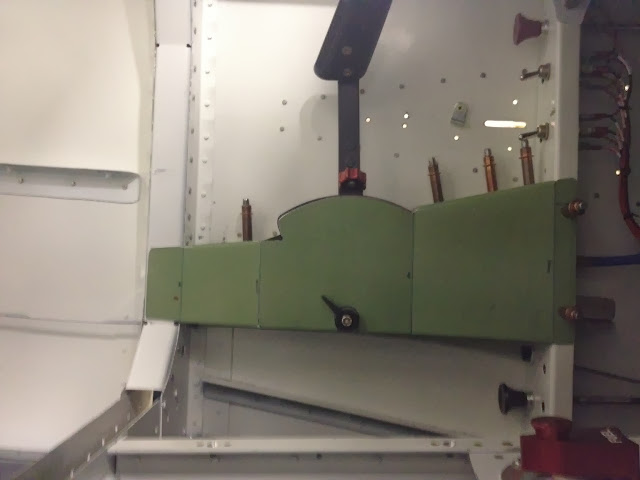
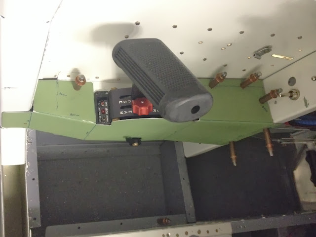
After a few weeks supporting formation flying, I am back to building. Like everything else on this project I keep over-thinking about possible solutions, hence the name DILEMMA for my plane. All I wanted to do was to install the remote ELT switch. I tried different locations then came up with this one after garage flying it for a while. It is out of the way of throttle operations and allows me to keep flying in an emergency. The remote switch is attached to a bracket under the side panel (not shown in pics).
N941WR
Legacy Member
That is a great location!
AX-O
Well Known Member
That sure looks nice! I have read the first 8 pages of your thread, if you would do it again, what would you do different?
Thank you for the kind words.
Would have built a rocket. All joking aside. I would do many many things differently. Some are documented on the link provided on post #1. Too many to list.
The next one will be better.
Last edited:
smokyray
Well Known Member
That's a big one...
Axel,
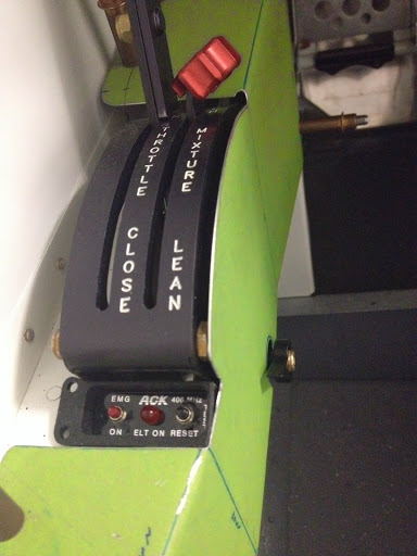
I have to say that's the closest to an F16 Throttle handle I have seen on an RV yet, nicely done!
http://www.aerotronicsllc.com/f16throttlegrip.htm
V/R
Smokey
PS:All it lacks (as you know) is a bunch more buttons and switches...
After a few weeks supporting formation flying, I am back to building. Like everything else on this project I keep over-thinking about possible solutions, hence the name DILEMMA for my plane. All I wanted to do was to install the remote ELT switch. I tried different locations then came up with this one after garage flying it for a while. It is out of the way of throttle operations and allows me to keep flying in an emergency. The remote switch is attached to a bracket under the side panel (not shown in pics).
Axel,
I have to say that's the closest to an F16 Throttle handle I have seen on an RV yet, nicely done!
http://www.aerotronicsllc.com/f16throttlegrip.htm
V/R
Smokey
PS:All it lacks (as you know) is a bunch more buttons and switches...
Last edited:
AX-O
Well Known Member
Wanted to give you guys an update. I now know why there is much less info on the finishing stuff on the web as compared to an empennage or wing. Its because people just want to finish!! forget posting.
Electrical system:
All the smoke has remained in the boxes. The only thing remaining is making the antenna wires (got the parts from SteinAir last week), running the wires and connecting the wing landing/strobe/nav lights.
Empennage:
Drilled the elevator horns (took forever) and set up the elevator rudder travel angles/stops. I still need to fill the tips.
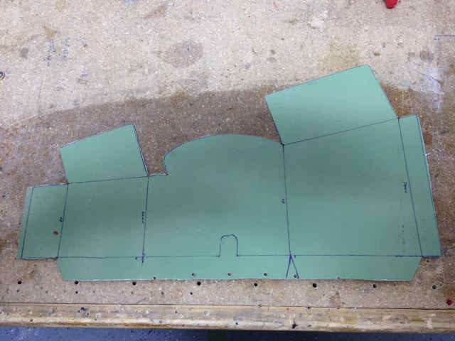
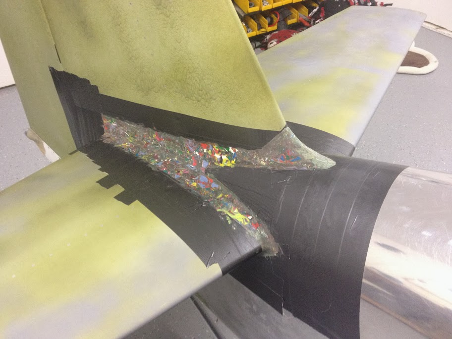
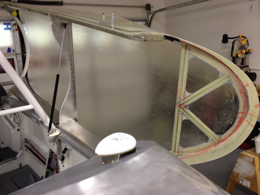
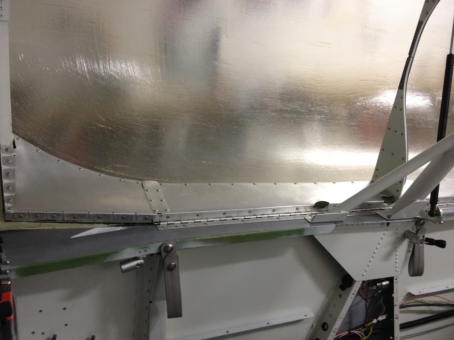
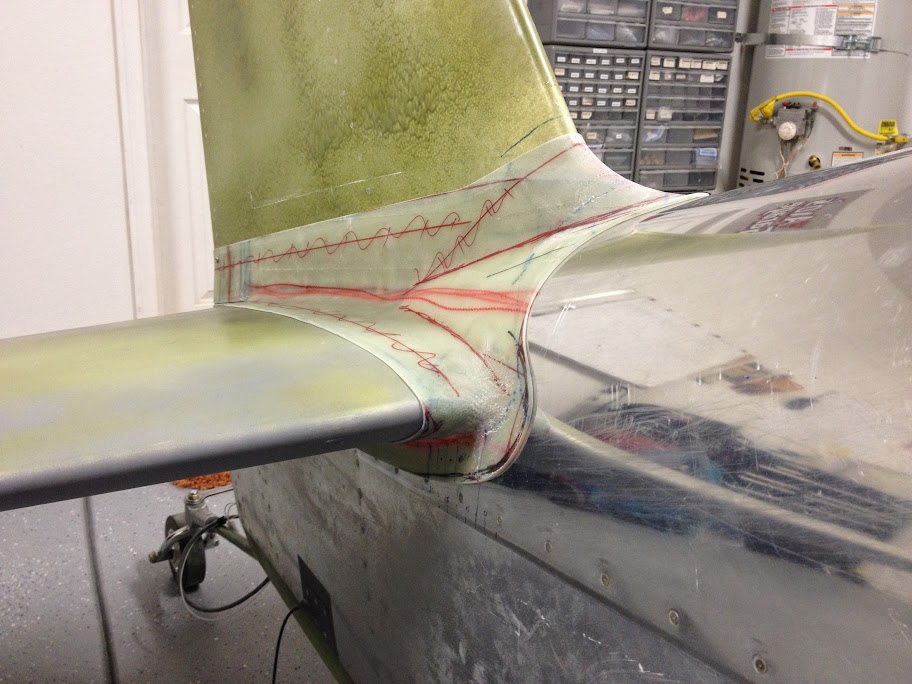
I am finalizing the empennage fairing. Trying to figure out how to cut it and mount it. The small metal plate shown in so the tape between the Vert and hor stab can be stiff. it goes behind the tape (where the elevator horns would be).
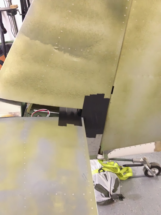
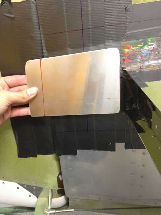
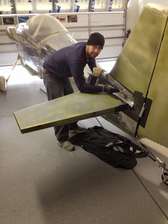
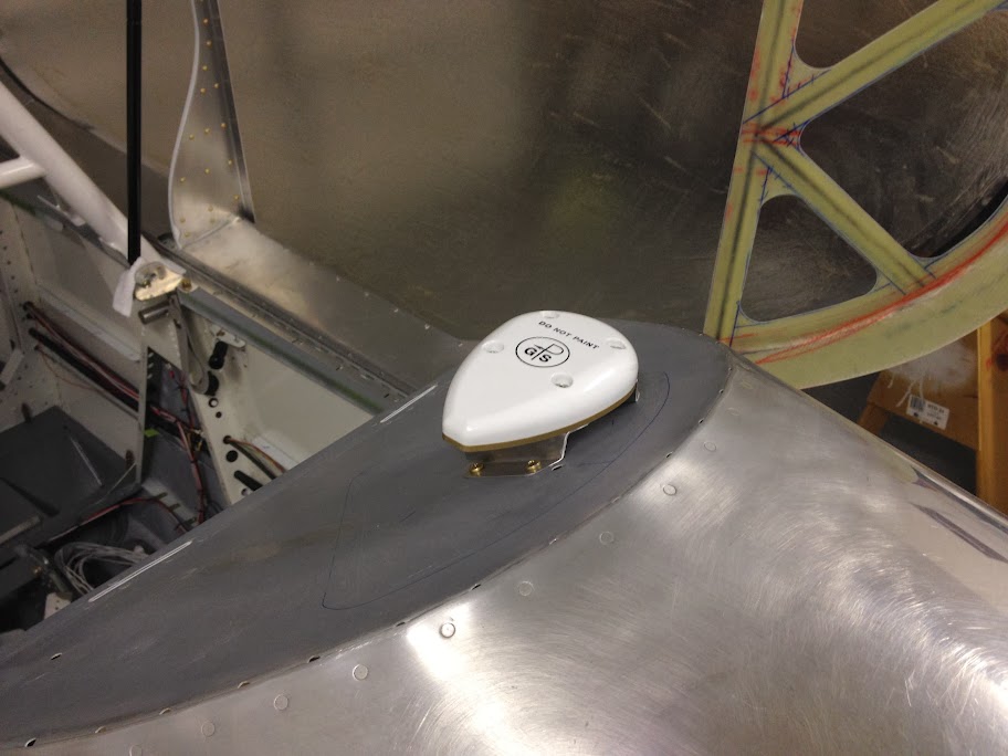
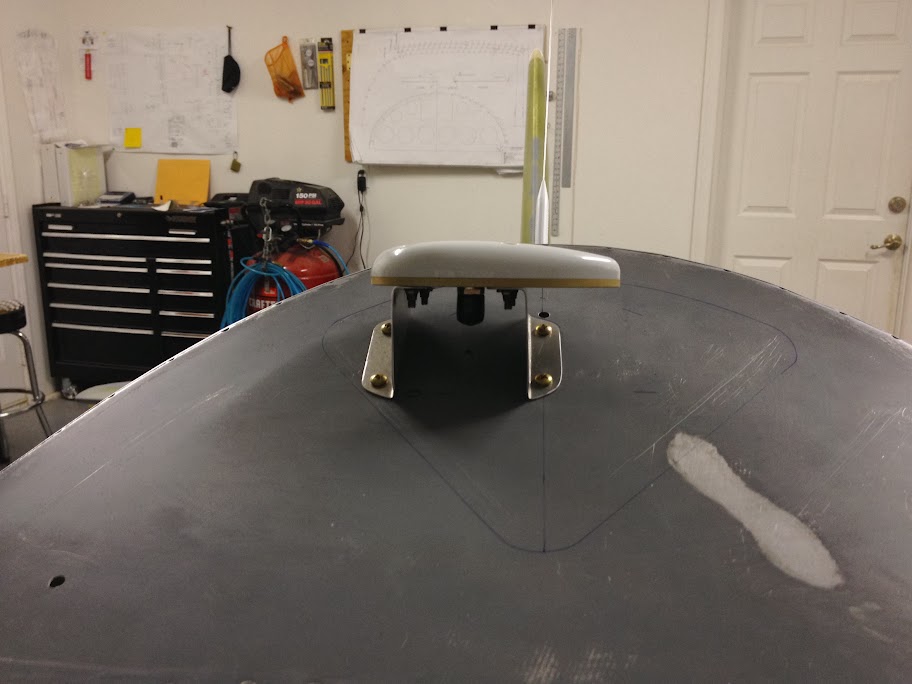
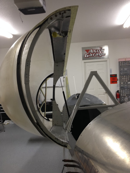
I mounted the GPS and the 406 ELT antenna. I almost cried when I cut the hole on top of my nice fastback turtle deck. The GPS antenna is not centered because of clearance for the canopy.
Cont post below.
Electrical system:
All the smoke has remained in the boxes. The only thing remaining is making the antenna wires (got the parts from SteinAir last week), running the wires and connecting the wing landing/strobe/nav lights.
Empennage:
Drilled the elevator horns (took forever) and set up the elevator rudder travel angles/stops. I still need to fill the tips.
I am finalizing the empennage fairing. Trying to figure out how to cut it and mount it. The small metal plate shown in so the tape between the Vert and hor stab can be stiff. it goes behind the tape (where the elevator horns would be).
I mounted the GPS and the 406 ELT antenna. I almost cried when I cut the hole on top of my nice fastback turtle deck. The GPS antenna is not centered because of clearance for the canopy.
Cont post below.
AX-O
Well Known Member
Cont from above.
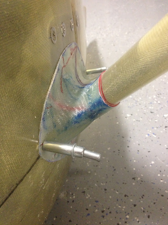
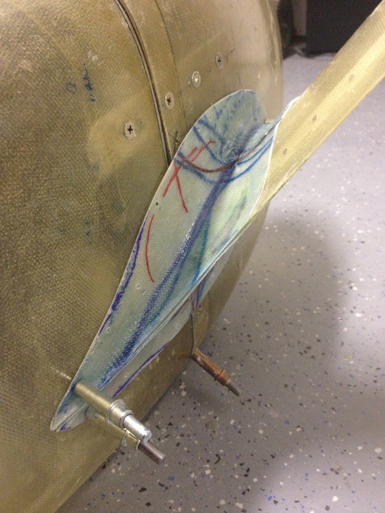
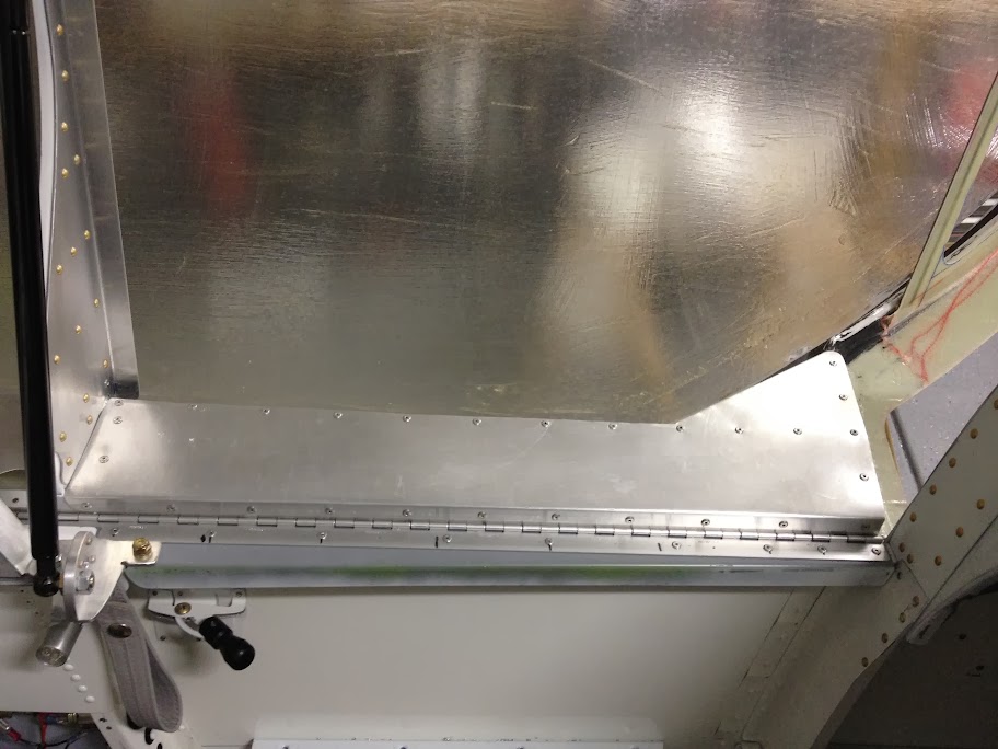
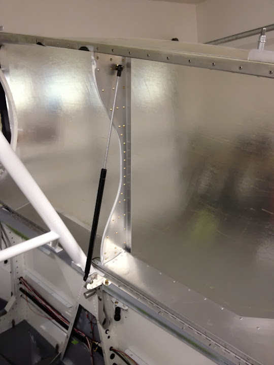
I also re-enforced the canopy skirts from the inside because the canopy was way too flexible for the winds around here. In doing that I changed the design of my canopy shock. There was too much torsional load on the canopy bulkhead. I made a support for the canopy on the aft portion out of carbon fiber arrows and fiberglass.
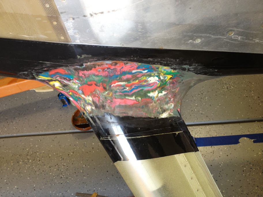
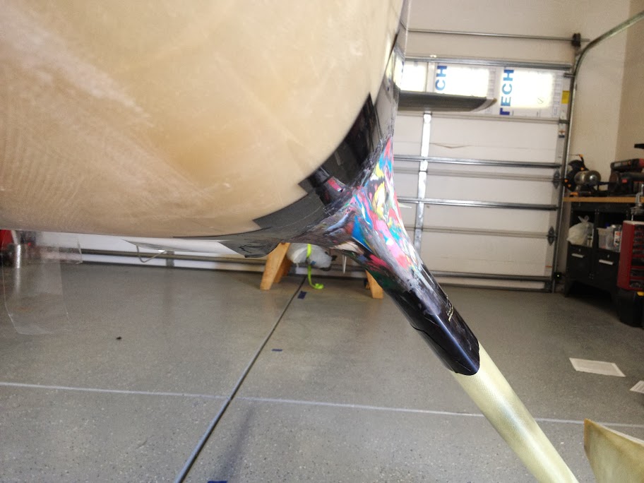
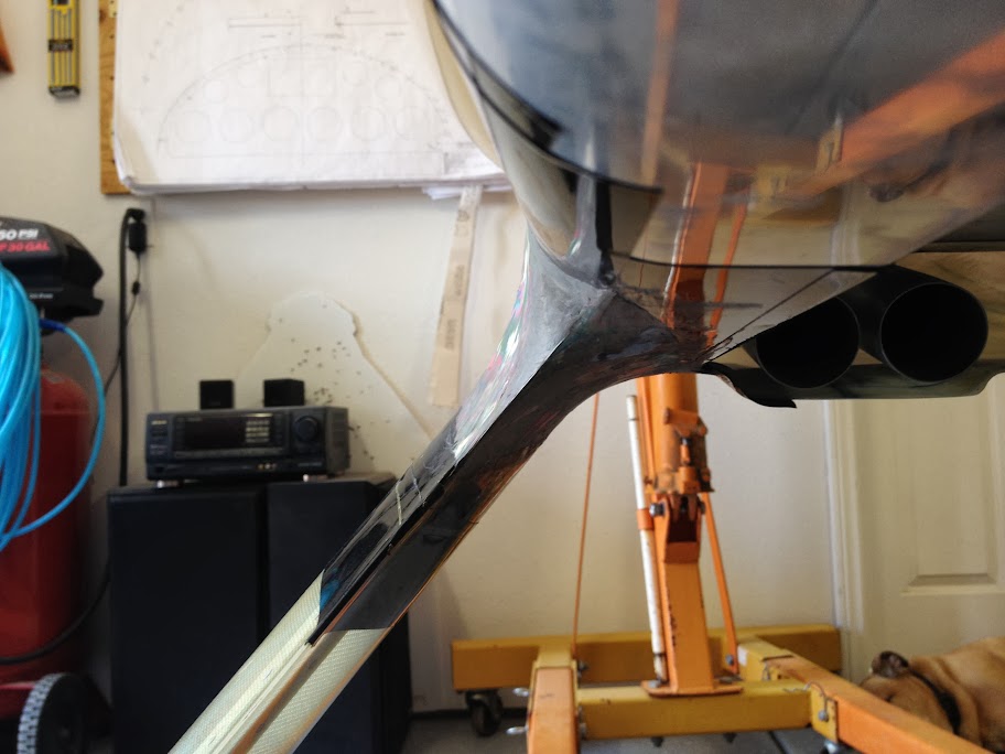
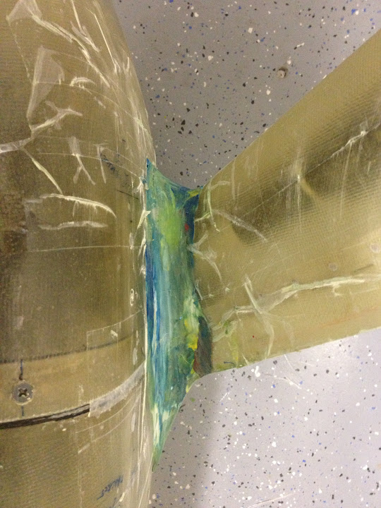
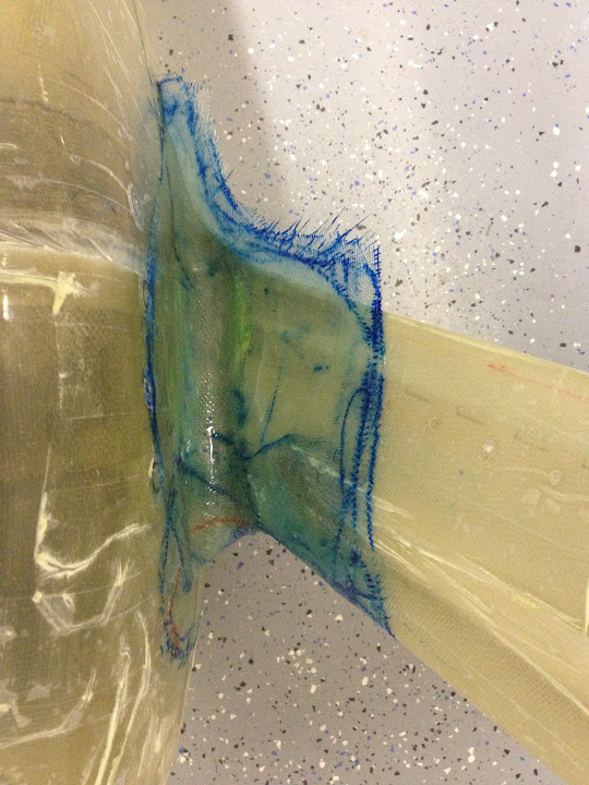
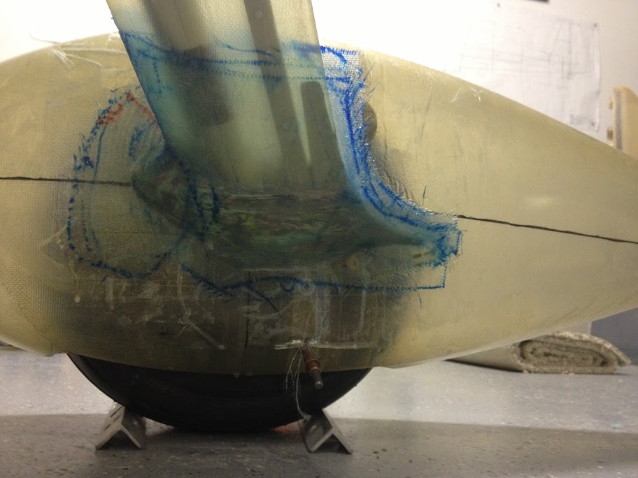
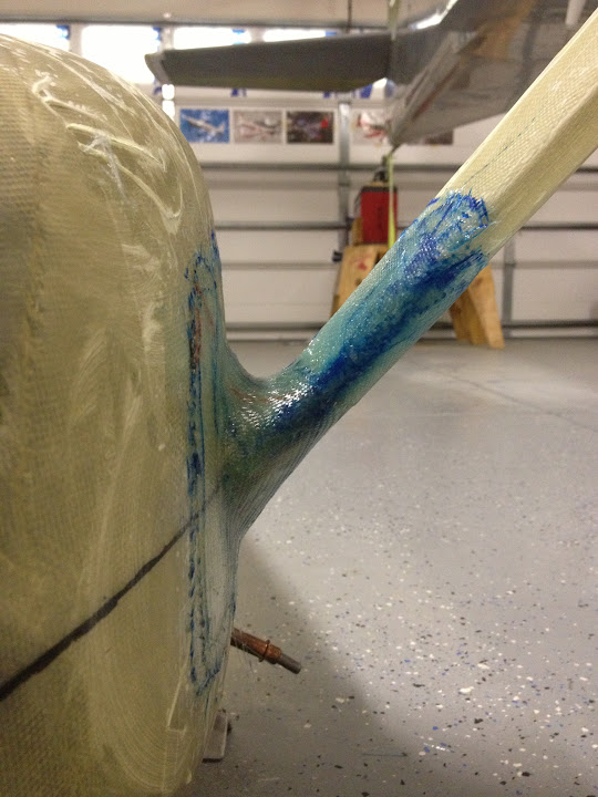
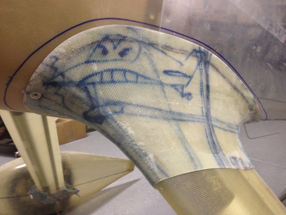
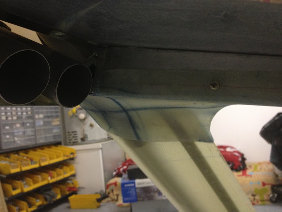
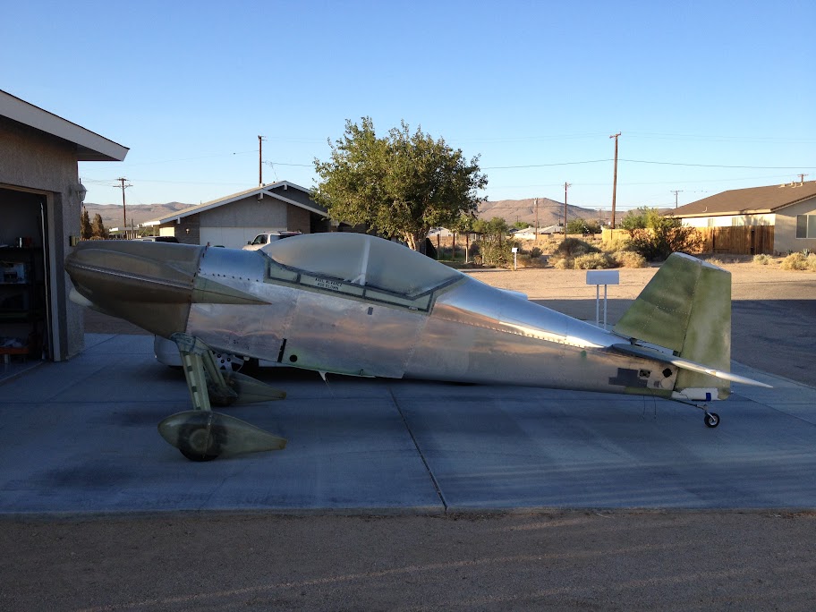
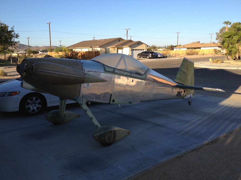
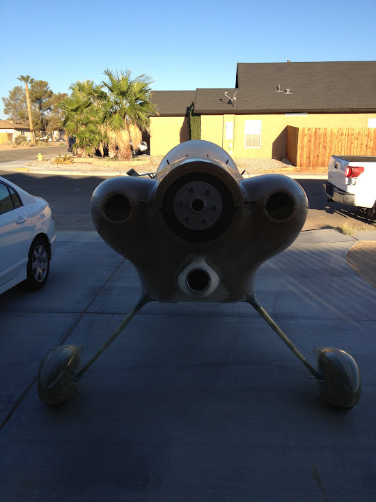
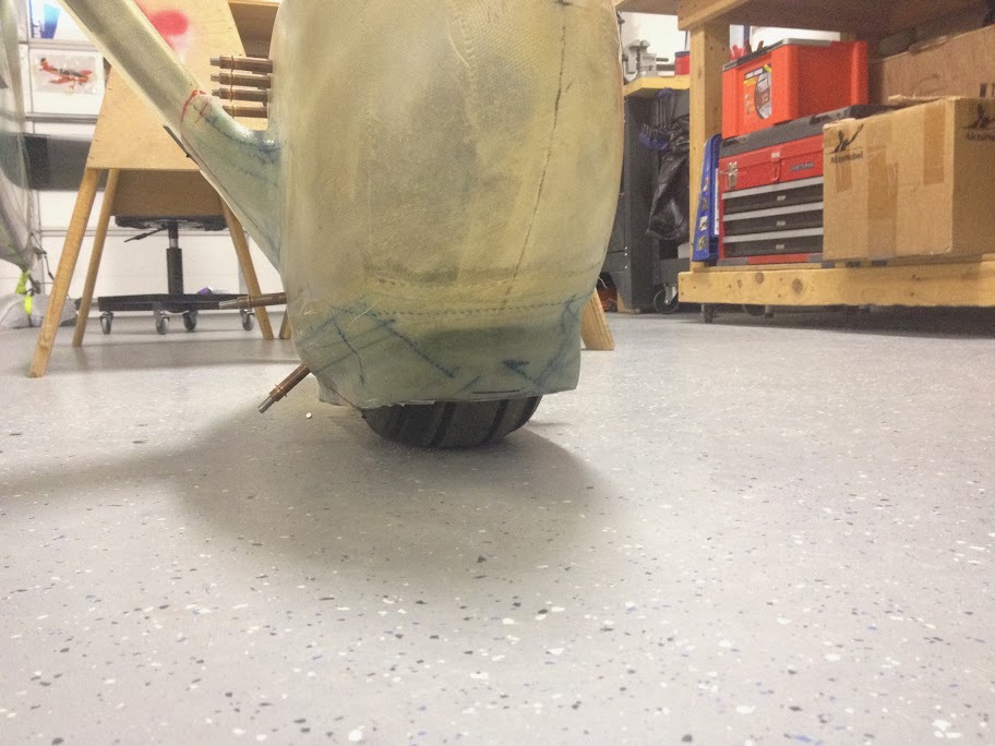
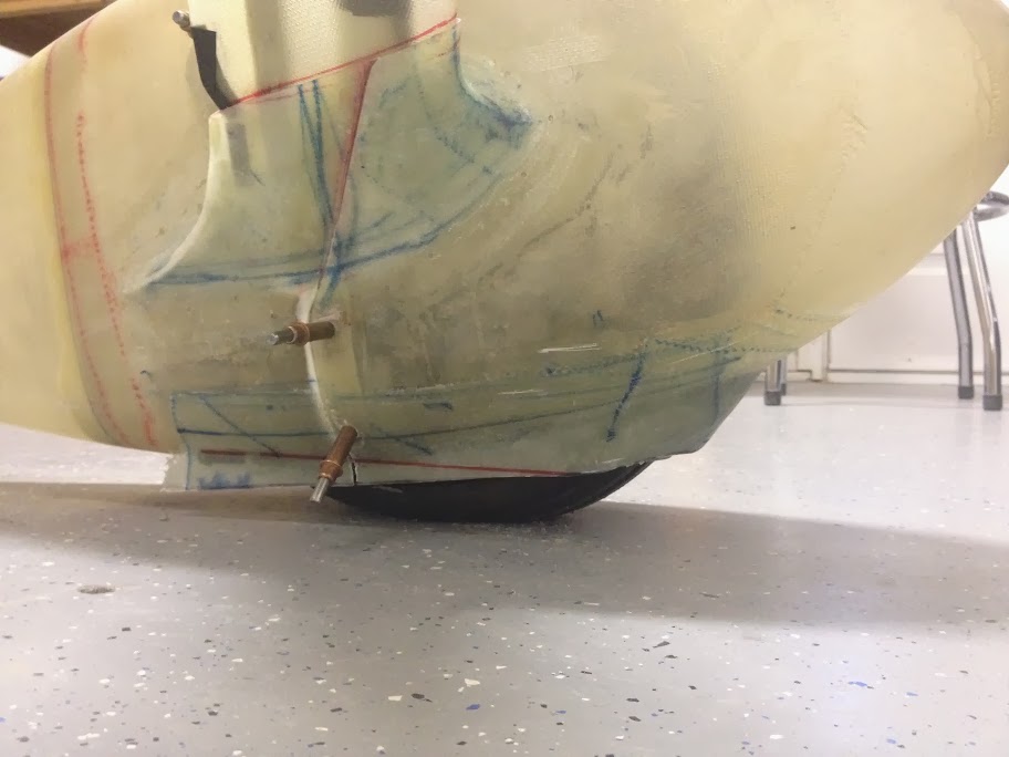
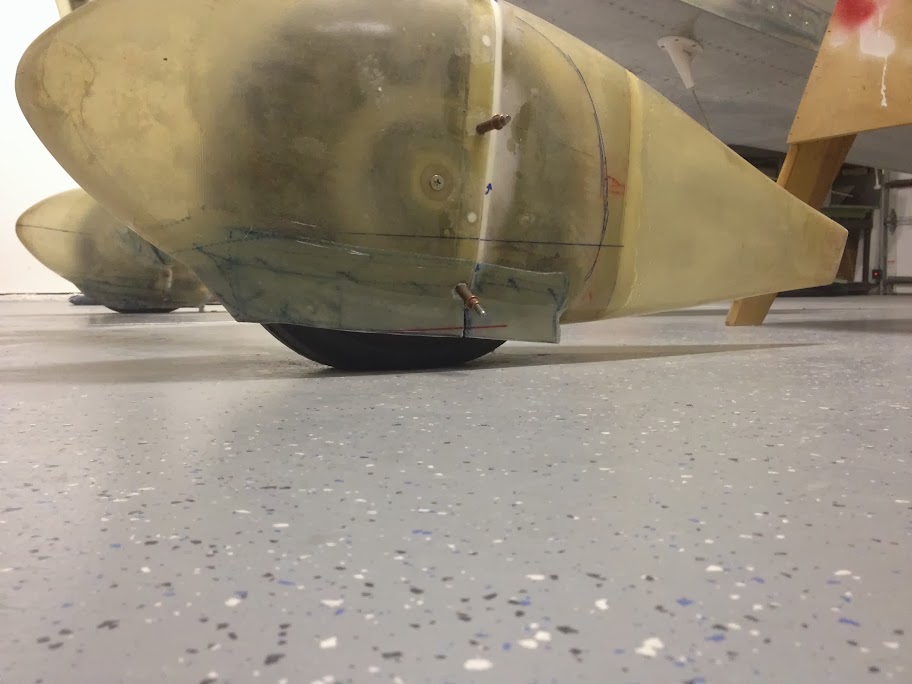
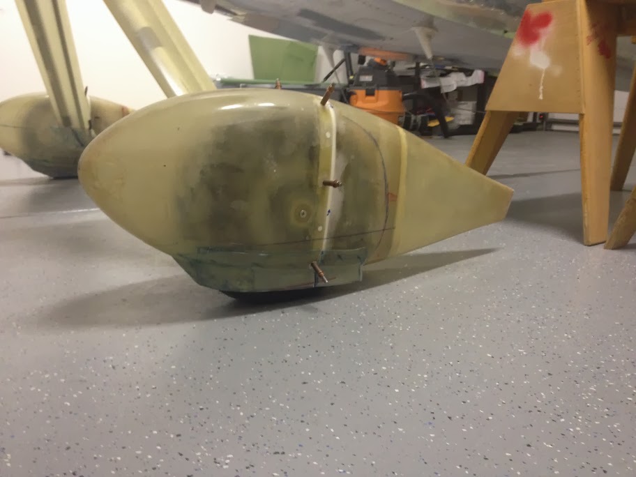
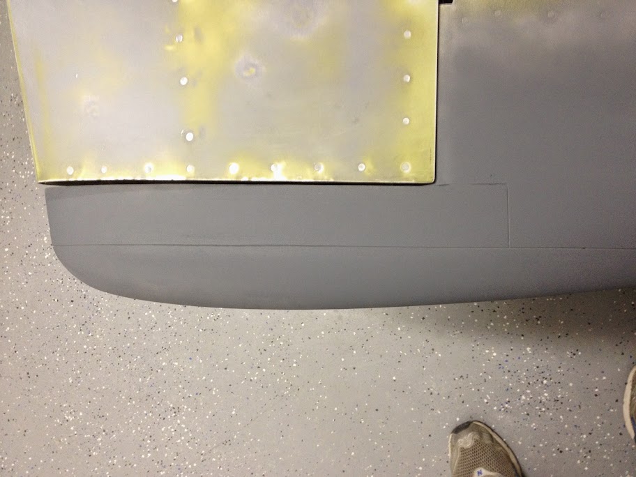
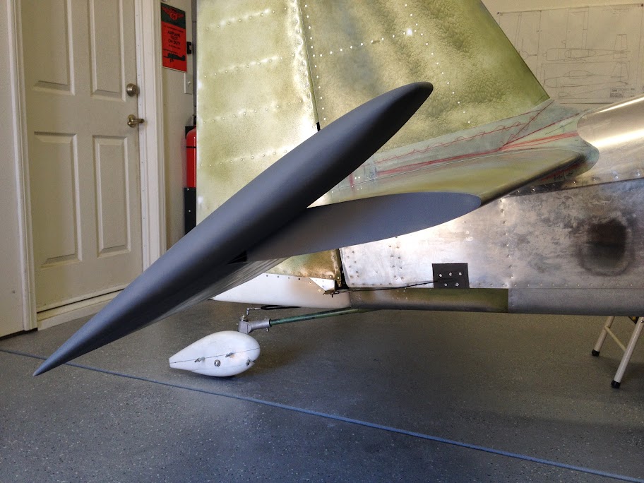
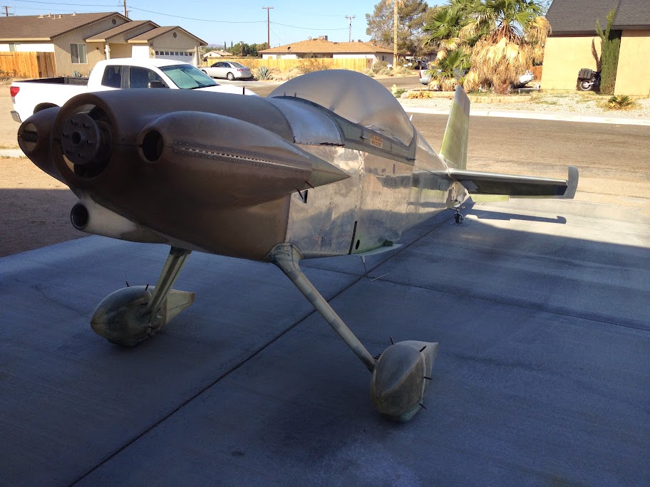
I am experimenting with a mod for my wheel pants to force the air around the tire vice letting the air figure out what to do in that location. I will cut the final shape once the wings are on.
I also re-enforced the canopy skirts from the inside because the canopy was way too flexible for the winds around here. In doing that I changed the design of my canopy shock. There was too much torsional load on the canopy bulkhead. I made a support for the canopy on the aft portion out of carbon fiber arrows and fiberglass.
I am experimenting with a mod for my wheel pants to force the air around the tire vice letting the air figure out what to do in that location. I will cut the final shape once the wings are on.
Last edited:
humptybump
Well Known Member
Axel - the wheel pant mod looks a bit like the extra sub-pants Bob Axom would add prior to a race.
http://www.vansairforce.com/community/showpost.php?p=214505&postcount=10
http://www.vansairforce.com/community/showpost.php?p=214505&postcount=10
acam37
Well Known Member
Axel, you stole my idea on the inside canopy skirts. I posted earlier that my welder messed up the canopy frame in a few spots, so we decided to skirt the inside to cover up those ugly beads. Glad you showed me how to go about making it happen.
As for the ELT antenna, I saw one builder here put the antenna under the rear empennage fairing. That's how I'm going to do ours.
As for the ELT antenna, I saw one builder here put the antenna under the rear empennage fairing. That's how I'm going to do ours.
AX-O
Well Known Member
Arlie,
If you are using a 406 elt, that location wont work. The GPS antenna won't easily see the sats. You can call me if you want to talk about it. Dont want to derail my build log.
The canopy has been done for about 2 months. Should have posted the pics sooner. I am way behind on pictures.
If you are using a 406 elt, that location wont work. The GPS antenna won't easily see the sats. You can call me if you want to talk about it. Dont want to derail my build log.
The canopy has been done for about 2 months. Should have posted the pics sooner. I am way behind on pictures.
Last edited:
Michael White
Well Known Member
Axel,
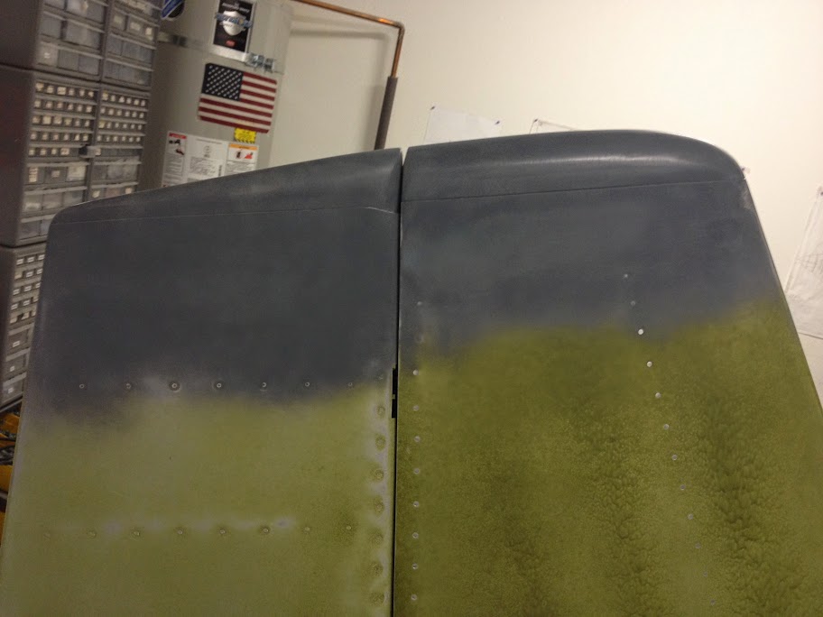
I had to look at this picture 3 or 4 times before I figured out that it was a darker layer of primer I was seeing, and NOT a major wrinkle in your VS.
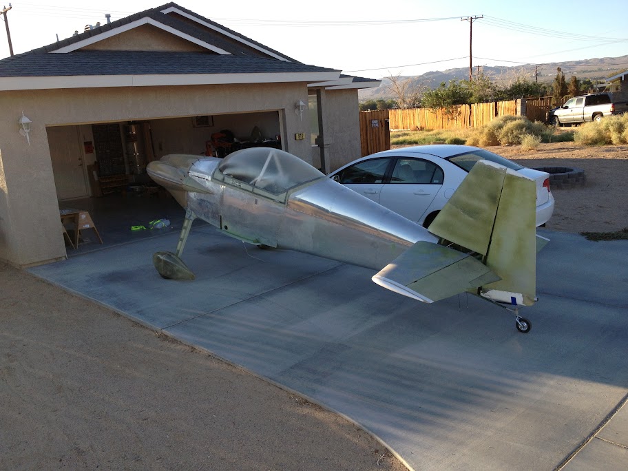
Progress is looking good, but I have a feeling your wheel pant extensions are only going to last one or two landings...
Dayton Murdock
Well Known Member
Nice Tail wheel
flyeyes
Well Known Member
That is not the final wheel pant configuration. Will let you guys know how it works out.
Axel, FWIW Ive thought about the wheel pants a lot. I have cracked my standard wheelpants landing on a very rough grass strip as the tires flexed.
My long term fantasy plan for the wheelpants involves making a female mold to a shape similar to what you've done, but using two part pour foam for the structure. The mold should give a nice smooth surface paintable by rattle can, and the foam would crumble harmlessly away if the tire flexed into it. It should survive a takeoff easily, and probably a few smooth landings. Not suitable for long term, but maybe for racing...
N941WR
Legacy Member
Axel,
It comes down to racing or grass strips. When I was building there were a number of posts stating that you gain 10 kts when you added the gear leg fairings and only five when you put on the wheel pants.
Thus I raised my wheel pants so I would have extra ground clearance on grass.
Maybe you could make those "spats" removable?
Holding up well so far, 350 hours. Zero tire gap, pant mounted very low. No flats yet. I run 50 psi to limit tire flex.

More here:
http://www.vansairforce.com/community/showthread.php?p=554319
More here:
http://www.vansairforce.com/community/showthread.php?p=554319
Last edited:
AX-O
Well Known Member
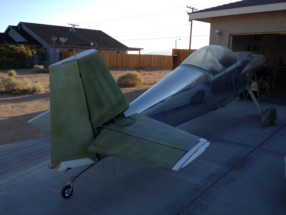
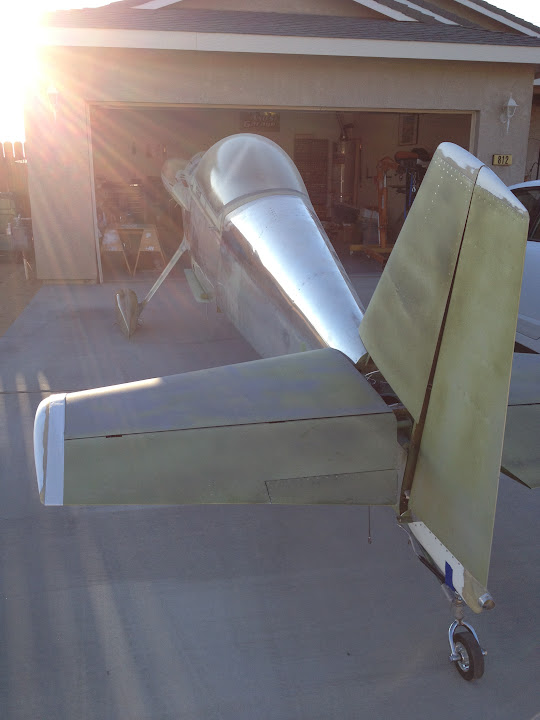
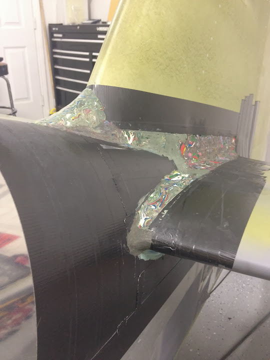
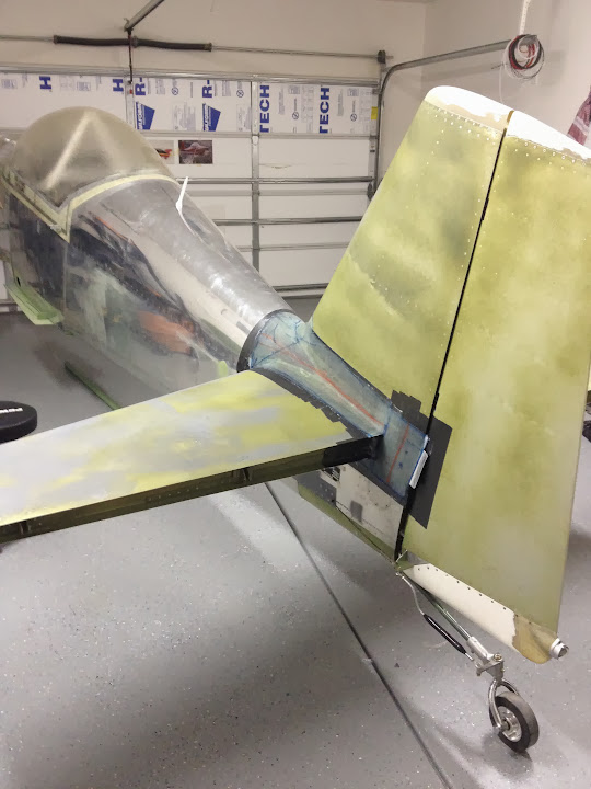
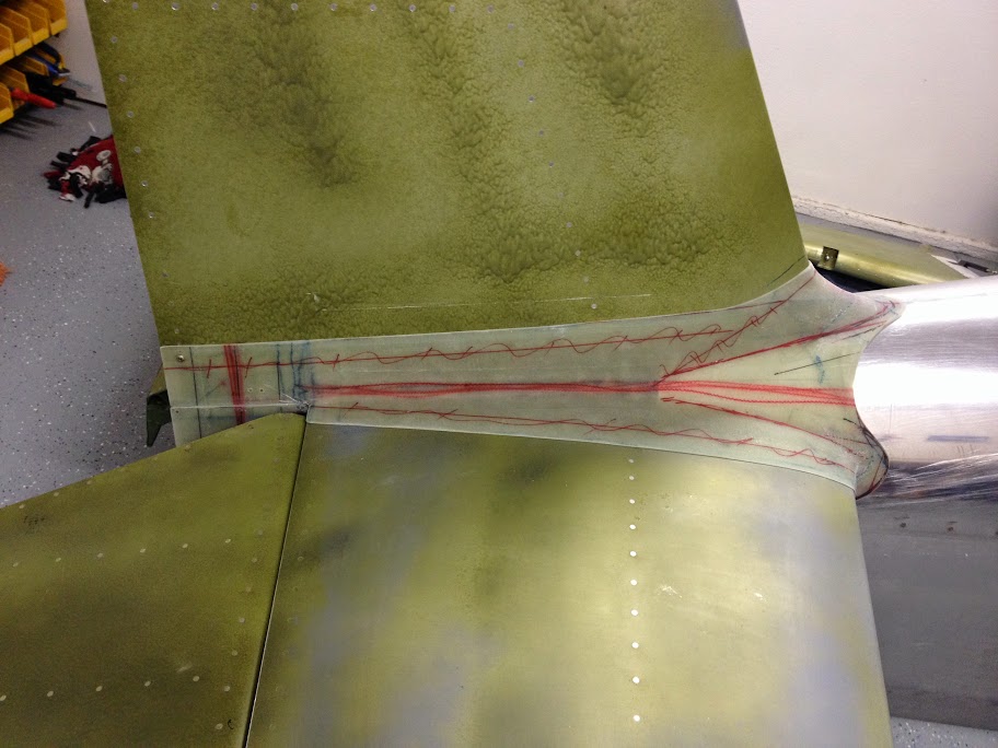
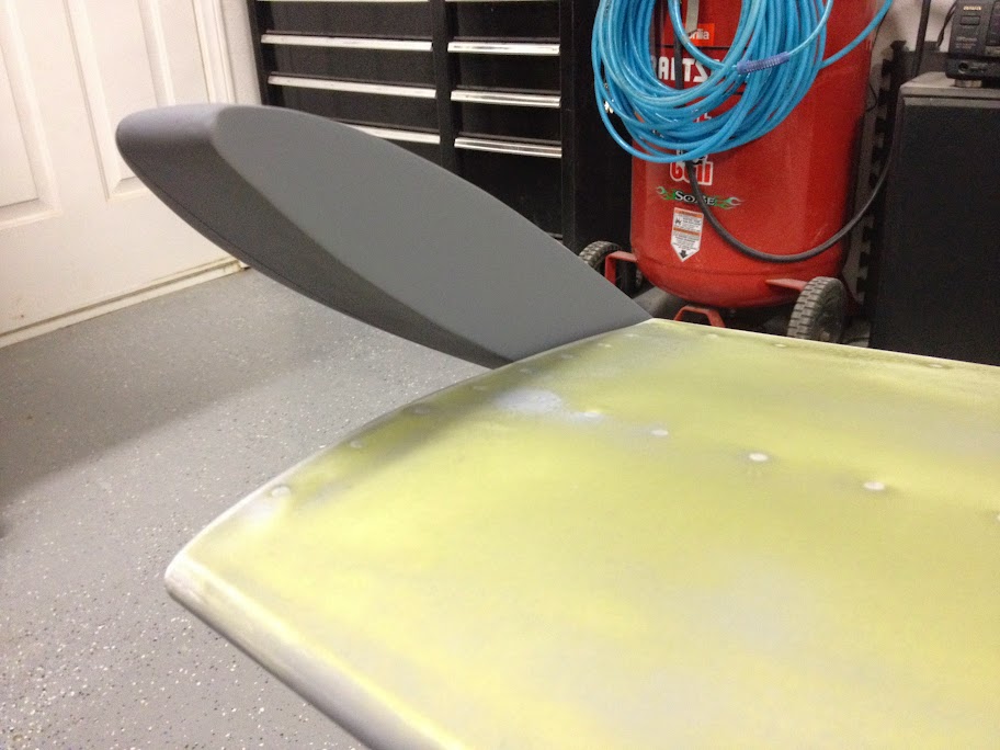
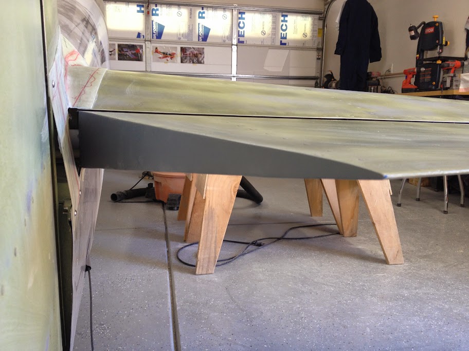
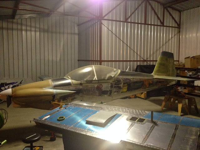
The progress now is less and less noticeable. I am working on small details such as antenna wires, EFIS set up, system checks and a couple of other cosmetic things. I hope I can move the plane to the hangar soon. Included are a few pics of the empennage fairing and the empennage.
AX-O
Well Known Member
Axel
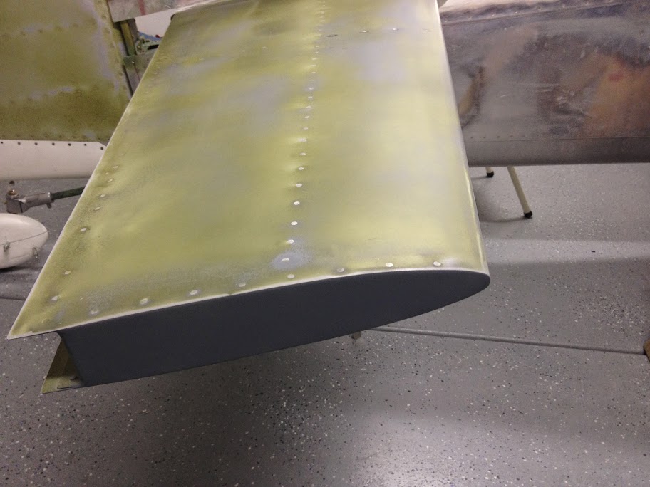
How did you fair the HS and elev. ends?
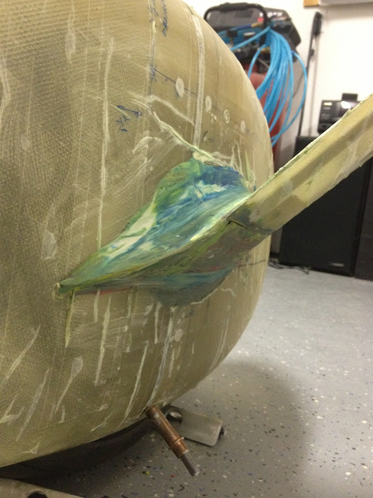
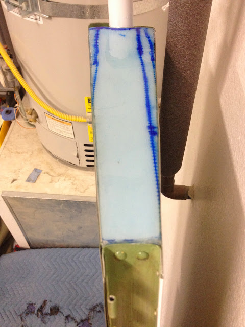
1. Grabbed leftover foam from my cowl cheeks.
2. Went to the end of the surface, placed the foam there and smacked it with a hammer to mark the contour of the control surface.
3. Cut the outline of the foam.
4. Mixed up some epoxy and flox (spelling?).
5. Placed epoxy mixture on the foam and tapped it into place.
6. Let the epoxy dry.
7. Sanded outside foam flush with control surface.
8. Laid 2 layers of unidirectional glass on the outside of the foam.
9. Sanded edges flush.
10. Filled pin holes with epoxy.
11. Primed.
It was way too much work. Not much weight but lots of work.
few of just foam.
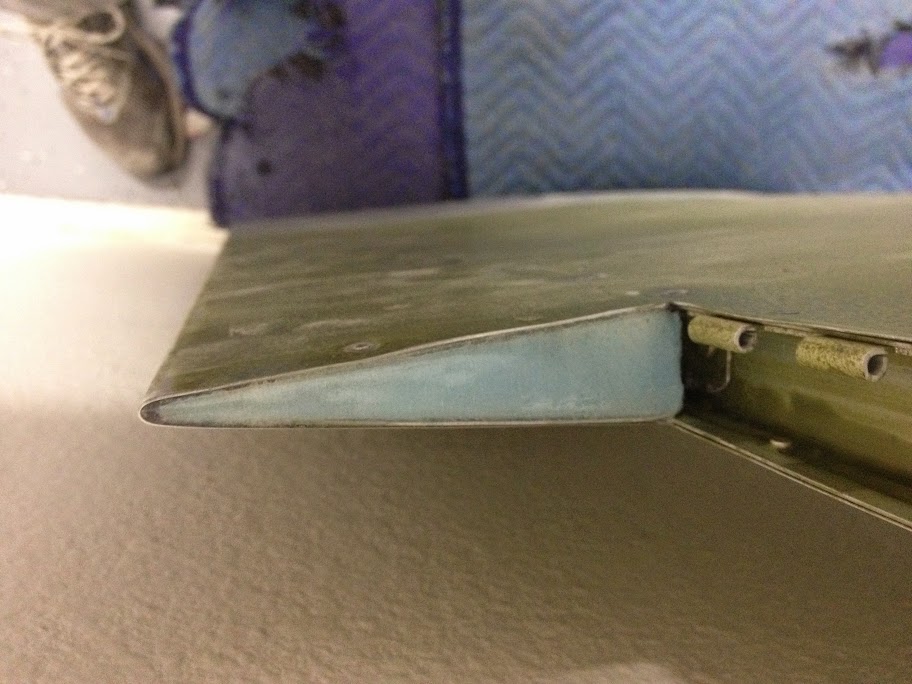
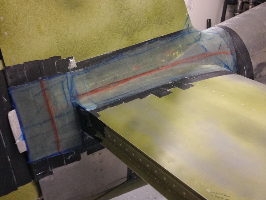
pic of glass and epoxy over the foam.
Last edited by a moderator:
AX-O
Well Known Member
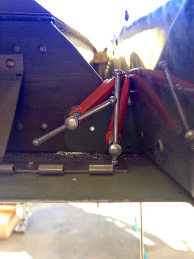
Just adding the thread of the purge valve return spring.
http://www.vansairforce.com/community/showthread.php?p=887162#post887162
http://www.vansairforce.com/community/showthread.php?p=887162#post887162
dukekimbrough
Member
rv 4 canopy
im interested in buying your canopy. 817-692-1805
im interested in buying your canopy. 817-692-1805
AX-O
Well Known Member
Just adding the link for the Big move.
http://www.vansairforce.com/community/showthread.php?t=117739&highlight=fastback
http://www.vansairforce.com/community/showthread.php?t=117739&highlight=fastback
AX-O
Well Known Member
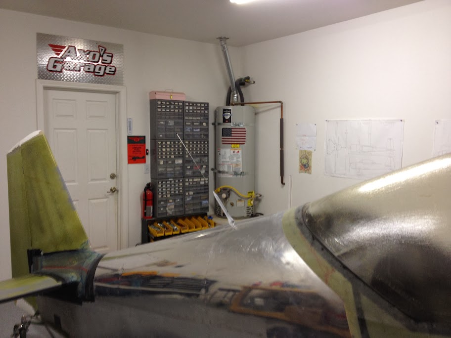
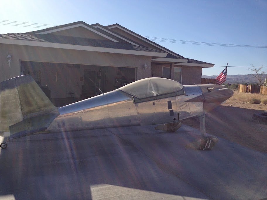
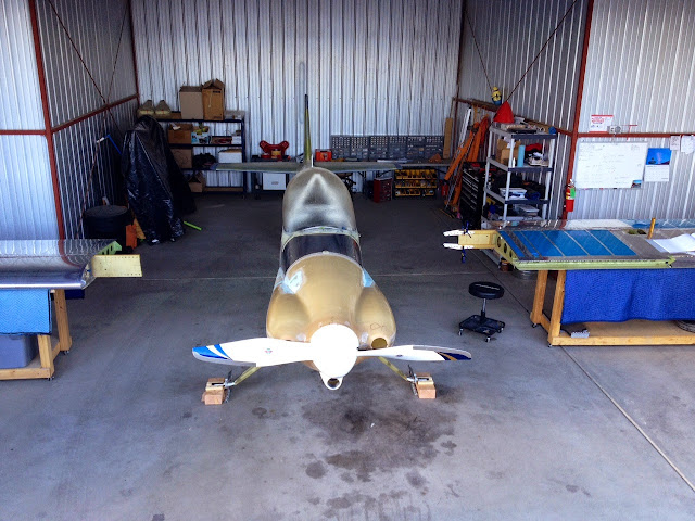
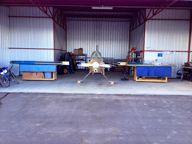
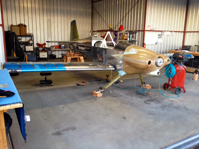
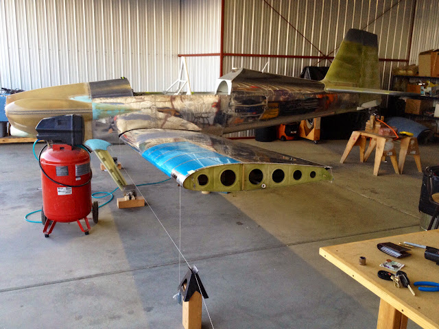
With the big move completed and the new shop set up, time to start working again. Last Sunday I was able to set the aircraft level on all axis. I put the main gear on 4X6 wooden blocks to minimize aircraft movement. I also made a platform for the tail wheel. Once the wings are on, I will level/check everything out again.
Last night I cut the control stick hole on the spar. Hopefully I can do the other wing tonight. The plan is for Dayton to come down on Sat and help me set the wings and drill the aft spar. I keep having nightmares about the 5/8 the edge distance on the aft spar.
Last night I cut the control stick hole on the spar. Hopefully I can do the other wing tonight. The plan is for Dayton to come down on Sat and help me set the wings and drill the aft spar. I keep having nightmares about the 5/8 the edge distance on the aft spar.
Last edited:
AX-O
Well Known Member
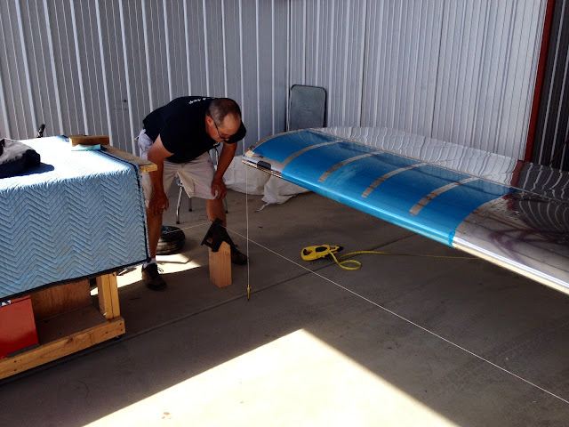
This weekend Dayton came down to help me set the wings and drill the 2 aft spar bolts. We spent all day on Saturday making sure the wings were squared, and the sweep and incidence were the same. We drilled a pilot #30 hole and walked away. We came back the next day and drilled to the final size.
Thank you Dayton. Would have taken me way longer by myself.
One step closer. Below are a few pics.
Thank you Dayton. Would have taken me way longer by myself.
One step closer. Below are a few pics.
Michael White
Well Known Member
Big step! Congrats, Axel!
With Dayton's help, I'm guessing that your wings are aligned to .001"....at least!
Great to hear you've got the wings on - keep up the momentum.
Paul
Great to hear you've got the wings on - keep up the momentum.
Paul
Greg Klema
I'm New Here
SJ Cowl
AX-O Have an -4 I completed 12 yrs. ago. Bronze Lindy Winner at Osh. It has a sliding canopy. I have made the big mistake of installing a SJ Cowl this winter. Don't know if this is proper, could we exchange e-mail addresses?
[email protected]
AX-O Have an -4 I completed 12 yrs. ago. Bronze Lindy Winner at Osh. It has a sliding canopy. I have made the big mistake of installing a SJ Cowl this winter. Don't know if this is proper, could we exchange e-mail addresses?
[email protected]

