Jimmie Kemp
I'm New Here
I'm installing a pair of garmin G5s and a GNX 375 in my RV8. I would like some advice on where to mount the garmin antenna and magnetometer. Thank you.


For the Magnetometer, I went with the end of the left wing. I've got a GRT, so not 100% sure that Garmin wants theirs to be as far away from ferrous metal like GRT, but physics are physics.I'm installing a pair of garmin G5s and a GNX 375 in my RV8. I would like some advice on where to mount the garmin antenna and magnetometer. Thank you.
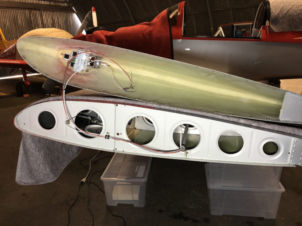
Thanks for the pirep Tom.I have flyled's nav/strobe in the tips and baja squadron pro landing lights with the Garmin magnetometer mounted on a right angle bracket mounted to the ribs at the mainspar. Works fine. No interference. ...
a pair of garmin G5s and a GNX 375
 fog to clear to flight test...
I'm installing a pair of garmin G5s and a GNX 375 in my RV8. I would like some advice on where to mount the garmin antenna and magnetometer. Thank you.

I'm not sure why shielding other wires would be needed since that is for e-fields. Twisting load conductors with the return current conductor makes sense, but not e-field shielding as a hard requirement for other circuits in the area (they may need shielding for their own reasons, but that is a different matter).....Also any electrical conductor running through the wing, should be twisted, shielded, and routed as far away from the GMU 11 and its wiring harness as feasibly possible.

