What's new
Van's Air Force

Don't miss anything! Register now for full access to the definitive RV support community.

All things cowling

LettersFromFlyoverCountry

Well Known Member
I learn by watching, less by reading. As I get set to begin the cowling on my RV-7A, I need to find a really good Web site where a step-by-step on the cowling installation has been well documented. Who's got the best site for such a thing?
 
Don't know (or think) it's the best, and it may be totally different that how you intend to do it, but here's where I started my cowling last summer.

Cowl beginning

Sorry I don't have my site grouped in to sections, but I spent all summer 2009 doing the cowl, so almost every day has something...
 
I found this one pretty good....

.... www.jeffsrv-7a.com/COWLING . this is a Vans cowl rather than a Sam James like Chad and I have. I will make the final "big cuts" on my lower cowl tomorrow, and will then be moving to the horizontal hinge installs . I've learned a TON in the last two weeks .... feel free to call me by phone anytime. I picked up one hint a couple of years ago I never forgot ... it has saved me lots of headaches. I'd be happy to discuss.
 
I used both Chad's and Brantel's sites. Most of the initial cowl fitting was pretty easy. it's the finish work that takes the time. Also my non standard setup seemed to require some extra work that wasn't very fun. I cut the air inlet ring and reglassed it for air filter clearance. Oh yeah then the pinhole rodeo.

here's pic from today. Daisy thinks it's coming along nicely.
RV-7build796.jpg
 
Cowl Tip

I don't have a web link, but I do have a photo that helped me. I followed Vans instructions and made a line 2 inches aft of the skin edge. This was fine, but the cowling was moving all over the place. I found it hard to sand down to a perfect fit, as the cowl changed position each time I took it off for sanding. Then a hangar talk with a fellow RV builder suggested that I secure the front of the cowling in position (see photo). Once I did that, it was easy to sand the aft edge into the shape I wanted. Filling the holes I used to cleco the front into position was very easy. Anyway, just something I found helpful for me.

IMG_5576.jpg
 
All cowls are not created (molded) equal

Or so it would seem. Which would make it harder to create a "how-to" website.

I have the pepto pink cowl. The lower cowl fit pretty well, the upper cowl was terrible. Besides the inlets being misshapen, there was a large and unsightly flat spot on the port side of the spinner hump just aft of the front face. That doesn't seem to be a universal problem.
 
Bob,

"I need to find a really good Web site where a step-by-step on the cowling installation has been well documented."

I was sort of hoping that would be your website after you do your cowl! - I'm right behind, about to start mine.
Bill Brooks
Ottawa, Canada
RV-6A finishing kit
 
Bob,
I was sort of hoping that would be your website after you do your cowl! - I'm right behind, about to start mine.
Bill Brooks
Ottawa, Canada
RV-6A finishing kit

Surely after my nearly 10 years of building you know that anyone who is ever "right behind" me in the construction process, is only there for a few minutes. :eek:
 
another cowling site

Thanks to everyone who's offered up Web sites. They've been helpful so far. The top is fitted. I started on the bottom today. Man, another set of hands would be nice. Anyway, I could use some sites for people who have nose wheels and are using hinges, rather than camlocks.

I used hinges and put up about 5 cowling pages and another 3 airbox pages. Hope these links can help somebody:

cowling page 1:
http://rv6aproject.ckhand.com/FirewallForward/Cowling/cowling_pg_1.htm

lower cowl airbox transition:
http://rv6aproject.ckhand.com/FirewallForward/Airbox/airbox_pg3.htm

links to this and other firewall forward stuff:
http://rv6aproject.ckhand.com/FirewallForward/FirewallForward.htm

Chris
 
Bob - have you tried these two?

Thanks to everyone who's offered up Web sites. They've been helpful so far. The top is fitted. I started on the bottom today. Man, another set of hands would be nice. Anyway, I could use some sites for people who have nose wheels and are using hinges, rather than camlocks.

http://www.matronics.com/rv-list/hovan/finish.html

and some brief notes here --

http://www.matronics.com/rv-list/bunnys-guide/rv/bunny/

Fuller RV-6A links referenced here -- 380+ "reads" in a few days so still a lot of RV-6x details being looked at...:)

http://www.vansairforce.com/community/showpost.php?p=460268&postcount=5
 
I grinded away on things today to try to get the front halves to fit as indicated on a few of the suggested Web sites. Brantel's in particular showed a beautiful fit.

Compare to this monstrosity:

canopy_aug22_1.JPG


If anybody in Minn., wants to make $100 for an afternoon of helping me figure this mess out,let me know. Until then, I think it's time to take a bit of a break.
 
Thanks, Paul, but I just can't figure out how to get those pieces to fit in there nicely. If I use the dremel any more to clean the flanges, it's going to come right through the fiberglass; it's getting very thin there; nothing like the fit I see on some of these Web sites.
 
Thanks, Paul, but I just can't figure out how to get those pieces to fit in there nicely. If I use the dremel any more to clean the flanges, it's going to come right through the fiberglass; it's getting very thin there; nothing like the fit I see on some of these Web sites.

Ahhh, yeah....the truth is that you will very likely have to lay in some more fiberglass to get it to look the way you want it. One of the nice things about glass work is that if it isn't what you want, grind away that which ofends and lay in some more. It's also what I hate about glasswork....

Paul
 
I'm concerned that the poor fit is going to screw up the gap between the spinner black plate on the bottom. I notice that several people in the Web sites above refer to the instructions mentioning drilling the front flanges together and sticking clecos in there while fitting.

For the life of me, I can't find any reference in the instructions or the DWG 45 (I think it's 45) to that. Can someone point it out to me?
 
Page 12-4

Bob,

I am right there with you on this new "adventure". But I remembered seeing the step you mention and I think it is on page 12-4 of the written instructions for the RV7. (Section 12, page4)

Says in part: "Fit the cowl halves together at the front."
Next paragraph says: "Mark the screw pattern for joining the top & bottom behind the spinner. Clamp top and bottom together at the spinner and drill the screw locations . . ."

I will be doing that on the floor and will probably put a 2 by cut the height of the firewall as a sort of spacer to hold the top and bottom halves (that attach to the firewall) the proper distance apart.

HTH,

Allen Fulmer
 
I am right there with you on this new "adventure". But I remembered seeing the step you mention and I think it is on page 12-4 of the written instructions for the RV7. (Section 12, page4)

Thanks, Allen. An online acquaintance also sent me the RV-10 instructions for this process. Man, I wish Van's would provide all its instructions the way they do with the 10 (and, I presume, the "12").

Anyway, thanks everyone for the advice. Though it's 90 degrees -- again -- in the Twin Cities today, I have this clock in my head ticking re: the cowling because in a few months, it'll be too cold to do any meaningful fiberglass work until next spring.
 
Bob, buy a heat gun- looks like a hair dryer but don't try it for that or you'll really have your hair on fire!

It looks like you are struggling with making the upper and lower flanges inboard of the inlets mate up. Mine weren't even close. The flange/inlet interface area needed to go out about 3/8" per side on my cowl. I forced the parts together, then drilled straight into the spinner face where the upper & lower overlap, and installed a couple of 1/8" clecoes per side. Then applied the heat gun, mostly to the upper cowl part of the interface. It takes a lot of heat. When the parts cooled, I removed the clecoes and found the fit to be improved, but in the end I still had to slit the edges of the flange on the upper cowl and re-glass it to get it right.

I put up a few photos of my cowl adventure on a photo site. No captions, but maybe they'll help a little.
 
The heat gun really helps in this area. As far as flange faces matching behind the spinner, it is very easy to lay some glass on the inside side of the flange face and grind/sand back that face as necessary to have them match.
 
I used the heat gun a bit on it today. I'm also doing some sanding on both pieces, and then reinforcing the location (where it gets thin) on the opposite side with layers of fiberglass. I guess it'll get there... eventually.
 
...... I guess it'll get there... eventually.

every step gets you closer (oops strike that)...most of the steps get you closer.

also remember, it's fiberglass any mistakes are temporary.

It won't be long and you'll be here, thinking about color combos and striping layout. the fitting and pinholes will be long gone.
RV-7build818.jpg
 
Says in part: "Fit the cowl halves together at the front."
Next paragraph says: "Mark the screw pattern for joining the top & bottom behind the spinner. Clamp top and bottom together at the spinner and drill the screw locations . . ."

I will be doing that on the floor and will probably put a 2 by cut the height of the firewall as a sort of spacer to hold the top and bottom halves (that attach to the firewall) the proper distance apart.

Exactly right.

Overlap the sides. Don't trim the top to the bottom or vice-versa.....trim either or both to an imaginary line which exactly bisects a 13" circle. The small white tabs set equal inlet size, ie a level split line. When trimmed install a single cleco as far back inside the inlet as possible. Doesn't matter if it is in a screw location; you can fill any extra hole later.

Cowl%20Initial%20Trim.jpg


Cowl%20Trim.JPG


Move to your engine. Attach a steel or aluminum tab to the forward baffle attach points (1/4" screw) above each front cylinder. These support the nose of the upper cowl. The rear is supported by overlapping the boot cowl. Draw a centerline on the top rear center of the cowl. Draw a matching centerline on the top of the boot cowl. Adjust the length of the front supports so the cowl nose is dead behind the spinner and perfectly level. Install a block to set the spinner gap. Align the centerlines at the rear of the cowl. Now trim the rear edge of the cowl so it sits on your hinge line or camloc tabs. The upper cowl is now where it belongs.

Fitting%20Top.jpg


Raise the lower cowl into position, again overlapping the sides. Install the two front clecos, and run a strap around the halves. Mark and trim the rear edge of the lower cowl. This may require a few on-and-off cycles.

Now trim the sides. Start by drawing a level line back from the front of the cowl where you had already established a bisect line in the very beginnning. Trim both halves to this line.

Cowl%20Fitted2.jpg


From here it's fine tuning and fasteners. Works for any cowl; did a Rans S7 with the same proceedure a few months back.
 
Last edited:
DanH;461049trim either or both to an imaginary line which exactly bisects a 13" circle. [/quote said:
As near as I've been able to tell -- at least on my cowl -- is this point is the molded edge of the bottom cowl, and the bottom of the top cowl at that location.

When you say "when trimmed" are you saying the flanges are trimmed? Because the instructions say not to trim anything on those flanges.

I am SO dead in the water right now. :confused:
 
.. is this point is the molded edge of the bottom cowl, and the bottom of the top cowl at that location.

As delivered, maybe, maybe not. The only references I suggest using are fundamental; the 13" circle and the upper edge of the cooling inlets. If required, adjust the location of the joggle and cowl edge to match the imaginary line.

When you say "when trimmed" are you saying the flanges are trimmed? Because the instructions say not to trim anything on those flanges.

They do eh? Well, frankly my dear.......
 
Last edited:
They do eh? Well, frankly my dear.......

Ah, OK, that clears up a point of confusion. So setting the 13" diameter on the spinner hole is basically setting the vertical configuration with the two cowl pieces, and setting the height on the inlets is setting the horizontal config. Do have that right?
 
Think about what you want and build toward it. You want a nice round 13" diameter to match the spinner. You want the split line to bisect that diameter, so you trim either or both pieces as necessary to match the bisect line. Keeping equal dimensions at the inlets on each side just keeps everything level.

There's nothing sacred about those joggles. They were located in the factory mold by adding a strip of fill material, probably by eye, and there is likely more than one mold....plenty of variation possible in the finished products. They don't locate anything. Maybe they are in the right place, and maybe not. Change them, move them, cut them off and replace them....you know, build an airplane.
 
Last edited:
What cloth for cowl "mods"?

And I just thought aluminum constuction, wiring, fuel lines, plumbing and wiring an engine were tough!

So, this being my first foray into fiberglass work and understanding (now) that the cowl, as received, just appears to not need a lot of work other than the expected trimming, I need to order some stuff while I am studying all about this next phase.

I already have the following:
West System 105 Epoxy
206 hardener
pumps
cups
small squeeges
rotary cutter
flocked cotton fiber
cab-o-sil
a similar bag marked "GB" (glass beads?)
3" epoxy roller w/cover

So, what else will I need for the cowl?
What cloth (or tape), filler, etc.

Looks like I will be doing some of what Dan explains above.
 
Al, you're good to go. 7781 is a favorite keep-in-the-shop cloth. You shouldn't need much unless you start building ducts and dams for the Soob cooling install. 1" tape can be handy if you need to shim the cowl flush with the adjacent aluminum panels. Use 2" if you're going with camlocs.
 
Two questions:

(1) In fitting the bottom cowling, the instructions say to let the sides overlap the top cowling. But you can't fit the bottom cowling without tucking the front corners UNDER the top cowling, at least enough to get the clecoes back in the drilled holes on the spinner snout. Or am I reading the instructions wrong?

(2) Have folks with vertical induction found interference problem with the mixture arm and if so, what was your solution?
 
Last edited:
Just saw a -9A...

Two questions:

......
(2) Have folks with vertical induction found interference problem with the mixture arm and if so, what was your solution?

..with this problem.

It required an added, blended-in "bump" in the cowling.
 
I'll be the contrarian in the bunch. I fit the bottom cowl first.

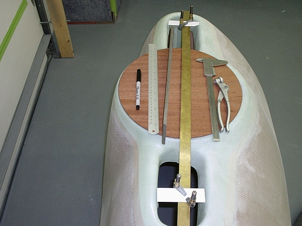
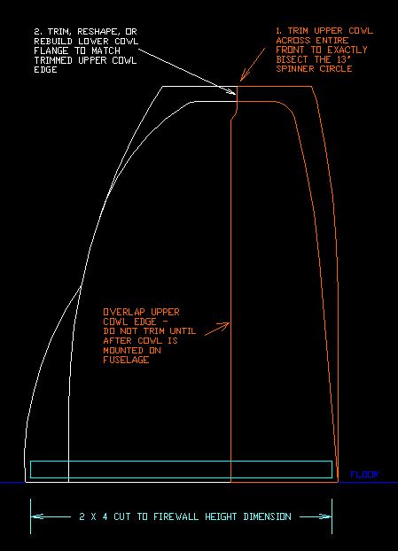
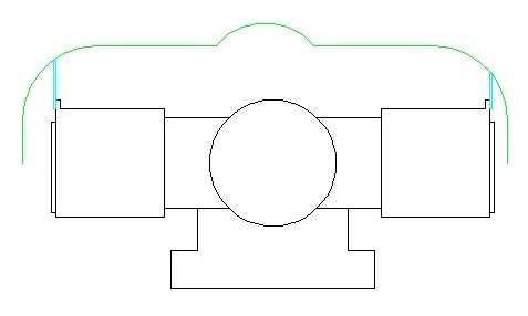
Before I did though, I made a 13" diameter disc out of plywood. I drew a line straight across the diameter. With the bottom cowl on the floor pointing up, I laid the disc on the cowl and aligned it with the spinner face, with the diameter line parallel to the joggle. In my case it turned out that the joggle lip (edge) aligned perfectly with the diameter line. In other words, the joggle lip formed a line that bisected the spinner, as I desired.

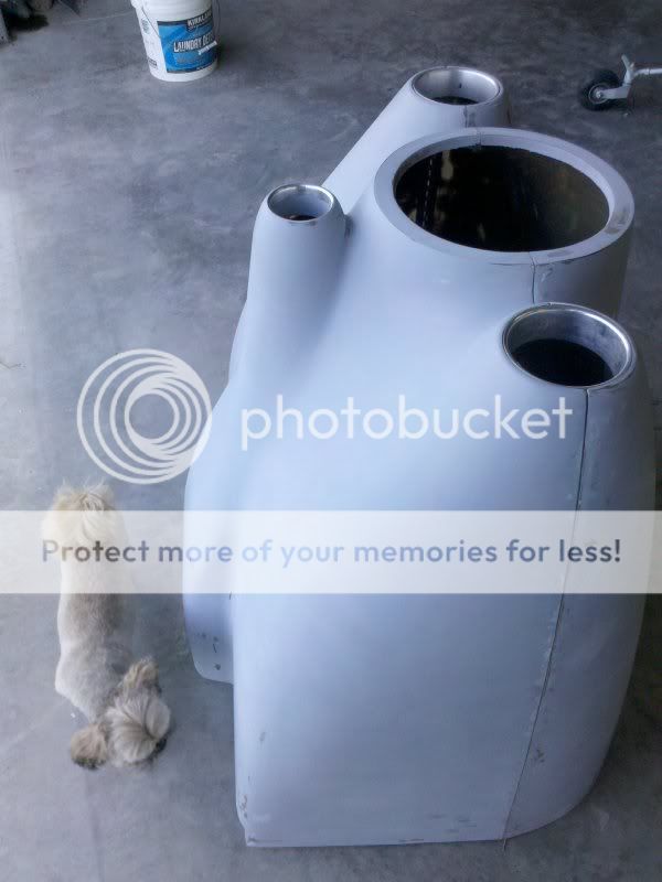
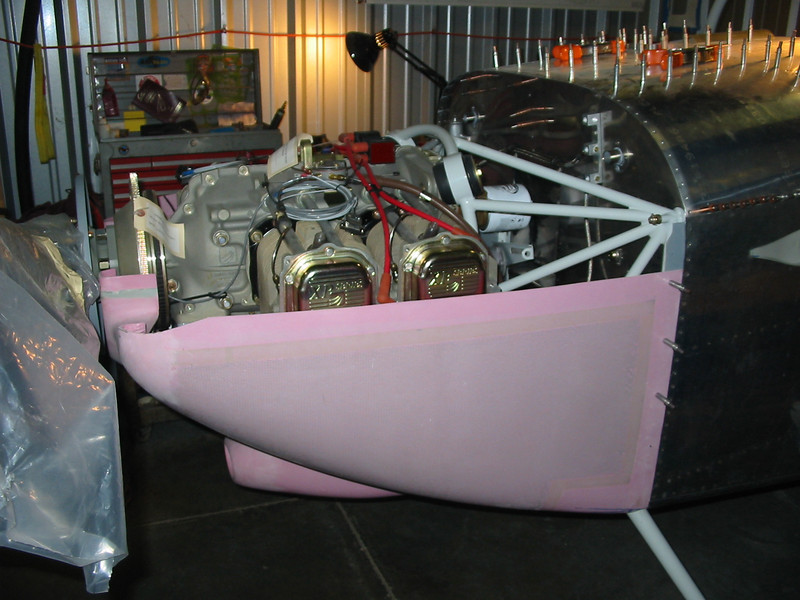
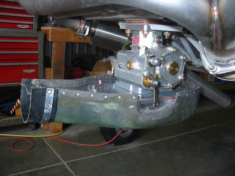
The outboard edges of the inlets and the sides of the lower cowl clearly extended up beyond the split line and would need to be trimmed. I laid a long straight edge across the joggle line and used a sharpie to extend the split line out to the outer edges of the inlets. Leaving some material for later trimming, I cut back the outer edges of the inlets so the upper cowl could be fit to the lower cowl. You can sort of see the trimmed port outer inlet in this photo:

850895070_qycs4-L.jpg


Keeping Dan's advice in mind, I iteratively heated/bent/trimmed the spinner interface of the upper and lower cowling, using my plywood disc and straightedge, until they fit together fairly well, without worrying too much at that point about how the flanges/joggles fit around the inboard edge of the inlets.

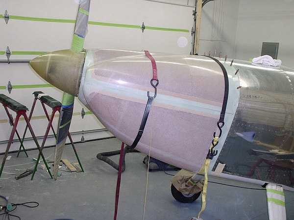
My rationale for fitting the lower cowling was as follows: At the front, the cowl has to match up with the spinner. At the back, the cowl has to fit the squared-off fuselage, which defines the vertical and lateral placement. No room for sliding around here. Since I'm building a tailwheel model, I had to trim the aft corners of the cowl to fit the gear legs, but that shouldn't matter for this discussion. I used a piece of 1/4" plywood, some strips of sheet metal and some spring clamps to locate and fix the front end of the cowl, and a thin ratchet strap around the engine and cowl to hold the back end up against the fuselage. I had previously marked a line on the fuselage per plans so that I could locate the trim line on the cowl. I'm using camloc strips which I had already attached, but with hinges the procedure should be similar.

I trimmed the bottom and side aft edges of the lower cowl, then drilled/clecoed that edge to the camloc strips.

Next, I started fitting the upper cowl to the fuselage. When I dropped it in place, it was obvious that the spinner face of the upper cowl angled forward severely. Drawing on courage obtained from the encouragement of experienced guys on this board, I cut most of the spinner face off the upper cowl, leaving it barely attached at the bottom on each side. I opened up enough of a gap that the face could push back until the face was parallel to the aft edge of the spinner flange and (surprise!) to the lower cowl face.

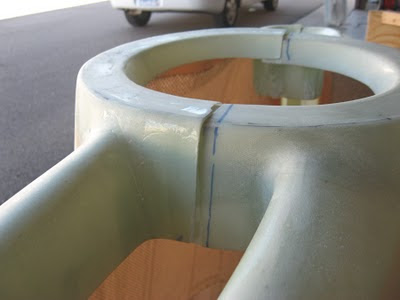
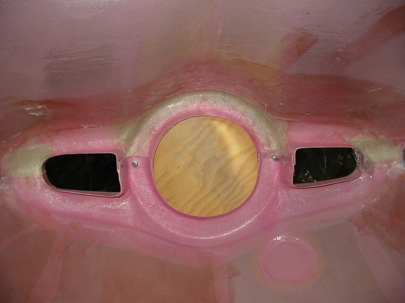
I drilled some holes along the sides where the upper overlapped the lower, for clecoes. That way, with the cowl halves off the fuselage, I could reassemble them correctly so they lined up as on the airframe. Using my plywood disc and the usual masking tape/epoxy/glass/filler I reattached the spinner face to the upper cowl. While I was at it, I created some fiberglass flanges, bonded to the lower cowl, to align the upper cowl at the outboard leading edges of the inlets. You can see some of the glasswork in this photo:

850895238_tVtUn-L.jpg


I don't have a photo showing those flanges.

After trimming the aft edge of the upper cowl as per the plans, I wound up letting the aft corners of the upper cowl define the aft starting point of the split line since the cowl was symmetrical within my ability to measure from side to side at that location, and it looked right. Making the cuts on upper & lower was a matter of using a piece of kit-supplied aluminum strip as a flexible straight edge (to follow the inward curve of the cowl towards the front), rough trimming with a cutoff wheel in a die grinder and finishing to an edge with a long sanding block.

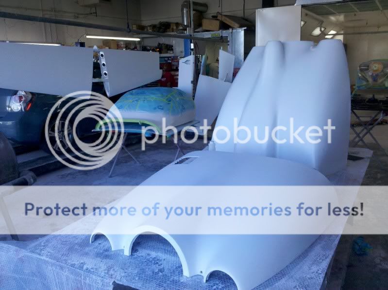
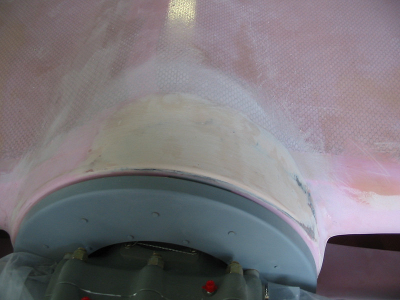
I then realized that the upper cowl had a big flat spot on it on the port side just aft of the spinner. Filling/sanding until it was symmetrical was a bit tedious, but I'm satisfied with the results. Somewhat visible in this photo:

912835275_i3e97-L-1.jpg


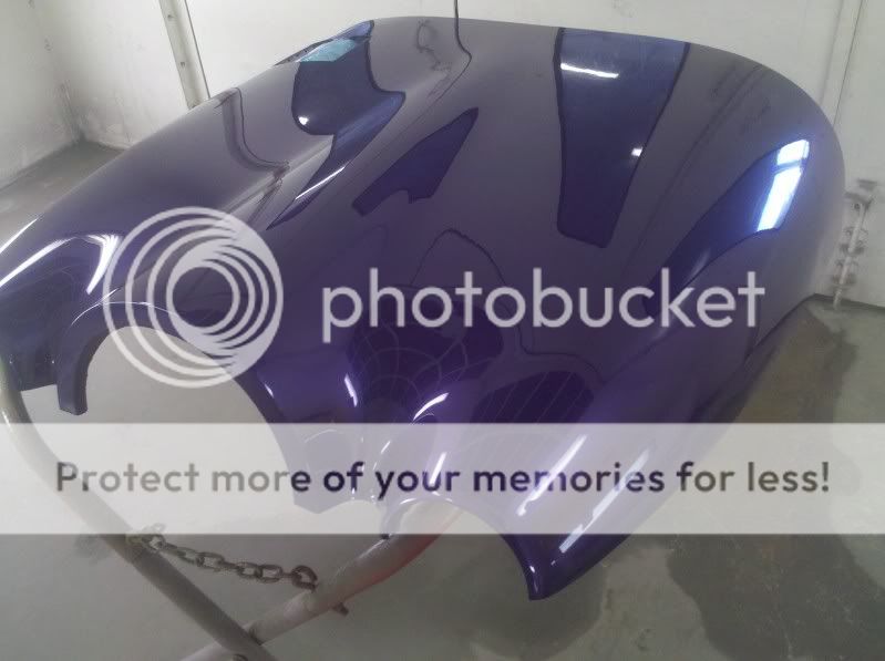
Still a ways to go, but with the oil door and the air intake done, it's starting to feel like it might be done someday.

I can drone on if anyone's interested. I didn't originate any of this. I give credit to the talented guys on this board who have done a good job of teaching and sharing, among them Brantel and DanH, for giving me the confidence I needed to dive in.
 
Last edited:
Nicely done Lars.

One point; there's a reason to hang the top cowl first. Recall I suggest installing two small temporary supports at the outboard front corners of the engine, then adjust the length of the front supports so the cowl nose is dead behind the spinner and perfectly level.

Two supports maintain a nose seam which is perfectly level in relation to the firewall.

A single support in the middle can allow the shell to twist, either because it was delivered that way or because of outside forces.

The bottom cowl shell is difficult to support at two outboard points in the front. There's a tendency to support it by clamping to the crank flange or spinner backplate....after all, that centers it behind the spinner. Sadly, clamping near the center won't eliminate twist.

Hanging either shell with a twist will alter the trim line at the firewall.
 
Last edited:
Good point, Dan. That's an important detail that I left out of my description above.

As it turns out, I was worried about that myself. I used a bubble level held laterally in several locations- against the bottom of the fuselage, held parallel to the split line defined by the front joggles, etc, to check for twist. My lower cowling was indeed a little twisted, but I was able to force the issue with my Rube Goldberg clamping setup at the prop flange. I should have taken a photo; it looked ridiculous, but it worked. I found that with the twist removed, the "un-twisting" propagated to the rear of the lower cowl and thus affected the trim line. No surprise there. With the aft edge clecoes in place (you can see some in my first photos) the twist was gone. Had I failed to notice though, I would've been grimacing every time I looked towards the cowl.

For what it's worth, I've seen a couple of pink cowls since I did mine. Neither had the nasty flat spot on the upper cowl like mine did, and the flanges around the inlets looked nicer. Go figure.
 
Two questions:

(1) In fitting the bottom cowling, the instructions say to let the sides overlap the top cowling. But you can't fit the bottom cowling without tucking the front corners UNDER the top cowling, at least enough to get the clecoes back in the drilled holes on the spinner snout. Or am I reading the instructions wrong?

(2) Have folks with vertical induction found interference problem with the mixture arm and if so, what was your solution?

Bob, I hope some of the preceding information helped with question number 1.

As for question number 2, I had that problem. In my case, the Superior-supplied P/A fuel servo had a downward-pointing arm that angled out and then down. The cable was to be on the inboard side of the arm. No way would it fit.

Lucky me, I have access to a TIG welding machine at work (and even luckier, I know how to run it). I cut the arm off the base, used a "hot wrench" (oxyacetylene torch) to straighten it, then welded it back on. P/A apparently sells an arm with the same geometry as I wound up with, but this was cheaper and faster for me. Sorry about the photo, it's the best one I have.

912834112_mfojJ-L-1.jpg
 
I have determined one of the problems. The instructions I have -- remember I've been building for 10 years --- were out of date. I'm now reviewing the current ones since they were rewritten to actually make sense.:p
 
Cut off the "jongles" aft of spinner

After studying all the stuff in this thread and reading a lot of posts about making new flanges for an oil door, I think I have decided to just cut the jongles off of the bottom cowl at the spinner.

It looks like it will be pretty easy to redo them after everything is hanging and trimmed. There is just no way they are going to fit together like they are and they are out enough that heating them up would not keep me from having to doctor up the flanges and joint anyway.

The top cowl is hanging and level (not twisted) so I'm halfway there? Right?

I have done all the "marking time" tasks (hinges where used, 1/4 turn retainer strips) so it is time to "cut or cut bait".

Hang in there Bob. We'll get it.

And thanks to all the responders that have gone before us and posted some encouraging words, pictures, and sketches.

Allen Fulmer
RV7 cowl
 
Move to your engine. Attach a steel or aluminum tab to the forward baffle attach points (1/4" screw) above each front cylinder. These support the nose of the upper cowl. The rear is supported by overlapping the boot cowl. Draw a centerline on the top rear center of the cowl. Draw a matching centerline on the top of the boot cowl. Adjust the length of the front supports so the cowl nose is dead behind the spinner and perfectly level. Install a block to set the spinner gap. Align the centerlines at the rear of the cowl. Now trim the rear edge of the cowl so it sits on your hinge line or camloc tabs. The upper cowl is now where it belongs.

I made two even tabs in the hopes that this would help determine when the cowling is perfectly level. Was ready to cut, then realized the two cylinders are offset forward-to-back so the difference of a couple of inches would actually lead one side to be higher then the other.

I put glass back on the rear and decided to start over again because I wasn't happy that I couldn't get a 1/4" gap around the entire top cowl near the spinnner (unless I raised it to well above the spinner), so figured I'll set it as best I can...then just build it up later after I figure out the amount of engine sag.

Perhaps it would help if I wasn't chasing differences of 1/32". Or perhaps not.
 
I made two even tabs in the hopes that this would help determine when the cowling is perfectly level. Was ready to cut, then realized the two cylinders are offset forward-to-back so the difference of a couple of inches would actually lead one side to be higher then the other.

The reference for "perfectly level" is the trim line across the nose of the cowl established as the very first step (straightedge in photo). Did you complete that step?

The front supports are unlikely to be the same length. As stated, adjust the length so the upper cowl sits centered behind the spinner and level, with the centerline ticks on the rear cowl and boot cowl matched.

Obviously the airplane itself also needs to be level.
 
Last edited:
Bob,
I guess this means there will be an episode 2 of the "Cowling Chronicles".
Bill Brooks
Ottawa, Canada
RV-6A finishing
now warily circling the green, (not pink) (is there any difference?) cowling halves sitting on the floor
 
I put glass back on the rear and decided to start over again because I wasn't happy that I couldn't get a 1/4" gap around the entire top cowl near the spinnner (unless I raised it to well above the spinner), so figured I'll set it as best I can...then just build it up later after I figure out the amount of engine sag.

I had to slice the entire spinner face off my top cowl in order to get it to match the spinner, then glass it back on. Which really wasn't as difficult as it sounds. In fact it wasn't difficult at all, once I got over the discomfort of realizing I had to do it. My lower cowl on the other hand was good enough that I was able to get a ~1/4" gap all around with just a little fiddling.

I agree with Dan; if you don't establish the trim line first, you'll have no reference for leveling the cowl.
 
"Boot Cowl"?

Dan said,

"with the centerline ticks on the rear cowl and boot cowl matched."
boot cowl? :confused:

I assume the hinge line between upper and lower cowls should be parallel to the longerons and each side the same distance below the longerons. IOW, level in roll and pitch when the fuselage is level.

Allen Fulmer
RV7 cowling getting there
 
Right. Getting the trim line is a little funky because I'm still sanding and adding glass to get the spinner snout to fit perfectly first. I'll probably end up using the laser level to make sure it's level on the fuse.

Haven't done much this week toward Cowling Chronicles II because my strategy has been to forget about it for a week and go to the Minnesota State Fair (it's replaced Oshkosh as the highlight of my summer. I took vacation days from work to staff the MPR booth. I don't go to the fair. The fair comes to me):

bob_fair_hat.jpg


I think it worked. I have new enthusiasm to head back to the hangar! Maybe some elves came and got it put together.
 
Last edited:
Keep at it Bob, you'll get there. I had many days similar to yours, but later you'll see it's all worth it.

here's a motivational pic for you.
RV-7build977.jpg
 
Back
Top