

Glas467
Well Known Member
This is the 3rd in a series of posts about the Vision Microsystems (VMS) VM1000 & EPI-800 systems. As a reminder, I?m not a FAA certified avionics tech, just an avid experimental aircraft enthusiast & EAA member passing along what I?ve learned to the community that?s given so much to me. This post will dive more into the inner workings of the data processing units (DPU). I primarily discuss DPUs with screw type terminals but most aspects are applicable to the serial connector types as well.
The DPU is the system brain, a very robust & elegantly simple computer with two major components, the analog & digital PC boards. The analog board has the terminal blocks (see pics 1 & 2), accepts inputs from all sensors/transducers, converts the signals as needed for processing, & routes them to the digital board by a set of connecting pins in the middle of the DPU case. The early generation DPUs had these connector pins hard soldered between the 2 boards making them very difficult to dismantle for repair. VMS later went to a header pin & connector setup which allowed the main PC boards to be easily separated. The analog board has 3 signal busses each with its own processing chip: one for the EGT signals (terminal J1), one for the CHT (J2), & one that handles all the other engine data signals from terminals J3/J4. When it comes to physical abuse, the poor analog board takes the brunt of any punishment you or the aircraft dish out to it ? more on this later.
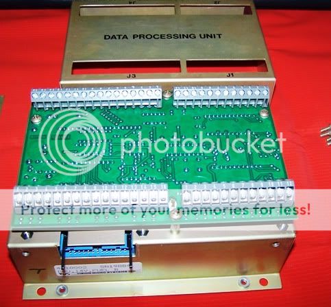
Pic 1 - DPU with Analog Board Cover removed.
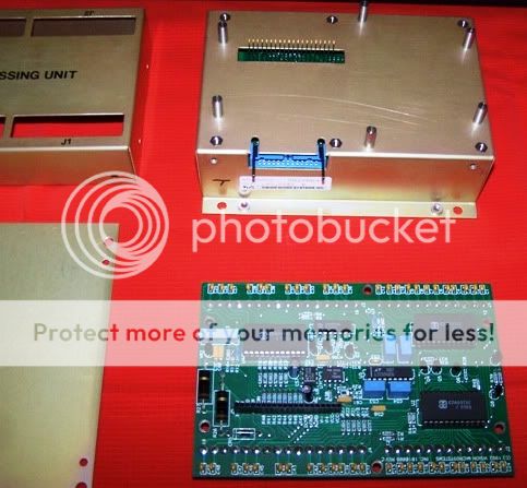
Pic 2 - Analog Board removed from DPU.
The second main component of the DPU is the digital board (see pic 3). The digital board accepts data from the analog board, analyzes it, & generates the appropriate signals to drive the cockpit indicators/warning annunciations. These signals output through the 26 pin rectangle connector to the ribbon cable assembly & the indicators. The digital board additionally houses the backlight subsystem which was covered in some detail in a previous article. Also mounted on the digital board is an integrated circuit (IC) chip affectionately known as the ?battery chip,? in reality is a multifunction IC consisting of the DPU?s memory, clock/timekeeper, plus a ?keep alive? lithium battery. Early generation battery ICs had limited service life due to an undersized lithium cell, sometimes lasting only 3 years before needing replacement; later an upgraded version addressed this. These early MK48T02B-20 chips are noticeably smaller than the subsequent replacement, M48T02-200PC1 (see pic 4). The -200 chips were an improvement over previous versions & had better service life on the order of 6-8 years, production ended on these some time ago. The current production chips p/n M48T02-70PC1 & -150PC1 feature lithium cells with a 10 year minimum life specification; owners have been getting good ?real world? service life out of these chips. Both are compatible with the VMS DPU processor.
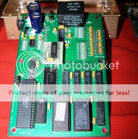
Picture #3 - Digital Board removed from DPU.
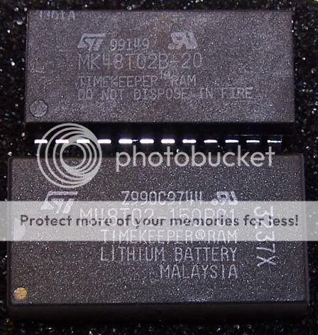
Picture #4 - Comparison of early chip (top) vs. modern battery IC (bottom)
So when does the battery need to be replaced? If you have a -70 or -150 battery IC, I recommend replacement at 10 years time in service even if it?s working fine ? you don?t want it to fail on you at the most inopportune moment. If you have a -200 ? just replace it now. Your DPU will give you hints that the battery is getting weak & reaching the end of it?s service life. On VM1000s, the initial indications are usually problems with ?lean find mode? being intermittent or not working at all & the fuel computer not accepting additional fuel & ?forgetting? the fuel tank size. On EPI-800s, the fuel computer symptoms are the same as above plus the DPU will lose the local time setting & your peak EGT function may not work. The final death throw with both systems is when the tach time is no longer retained, this indicates the battery is completely failed.
One other note regarding batteries ? I had a case of an owner who could not get his fuel computer to work on a VM1000, it would not accept a fuel tank size nor additional fuel. The owner had just paid $200 to have the battery chip replaced by his local avionics shop & he had successfully reset the tach time so he was sure the problem was in the DPU somewhere ? the avionics shop did not have expertise in VMS units so they contacted me. When I received the DPU & opened it up, it had a -200 battery chip in it ? I guessed the chip was at least 10 years old, a phone call confirmed it was stock that had been on the avionics shop shelf for a long, long time. I replaced the chip with a new production -70, ran a bench test & everything worked perfectly again.
As I mentioned earlier, the analog board is the first to take any damage on the DPU. In repairing DPUs, I?ve found bent or broken terminal blocks. This seems to happen either from dropping the DPUs during installation/removal or from trying to shoehorn the DPU into a too tight or otherwise inappropriate installation; avoid installations in inaccessible locations if at all possible. Also, remember that our aircraft have moving parts & carry people ? having a control rod impact your DPU, short out terminal connections, or having a passenger kicking the DPU because it?s mounted near their feet -- not a good thing. The engine compartment & battery bay are NOT appropriate locations for the DPU ? I received a unit recently that had extensive corrosion internally, DPU screw heads were rusted completely, all copper parts were corroded green & black, the analog board was delaminating, even plastic parts were discolored & blackened but amazingly enough it still worked! When I queried the owner, he said it was mounted near the battery ? battery acid & the vapors that come off the battery during charging are bad for your DPU! Also, over tightening the screw terminals result in stripping the small threads or actually breaking the screw off ? nice & snug is all you need.
The analog board is susceptible to static discharge damage. In two recent repairs, I?ve had to replace the analog signal buss processing chips ? I suspect the damage was caused by static discharge. When I discussed the installation with the owner, it became apparent that the DPU case was not properly grounded in the aircraft as directed by the VMS installation manual. Case grounding is critically important in composite aircraft such as Glasairs & Lancairs; metal aircraft such as RVs should get good case ground since they are mounted to the aircraft structure. After having the owner reinstall the DPU with a case ground lead, there have been no subsequent problems. Bottom line here is proper grounding protects your DPU & sensitive electrical equipment in general.
So how do you keep your DPU safe & happy? Grounding, grounding, grounding! Proper grounding is the first ingredient in good service ? follow the installation manual & make sure you have good case & system ground. Installation: make the DPU accessible & check it as part of your annual condition inspection, avoid areas where dirt/grime or corrosive gasses/fluids can invade the DPU. Screw terminals can loosen in service & lead wires can wear, during your annual give each terminal wire a gentle tug & check the torque with a properly sized jeweler?s screwdriver. Always discharge yourself & ground the aircraft before servicing any VMS components or any other electrical components.
If I can help you with DPU battery change, troubleshooting, or any other VMS issue, please feel free to contact me direct at [email protected]
Happy Flying,
Reggie
The DPU is the system brain, a very robust & elegantly simple computer with two major components, the analog & digital PC boards. The analog board has the terminal blocks (see pics 1 & 2), accepts inputs from all sensors/transducers, converts the signals as needed for processing, & routes them to the digital board by a set of connecting pins in the middle of the DPU case. The early generation DPUs had these connector pins hard soldered between the 2 boards making them very difficult to dismantle for repair. VMS later went to a header pin & connector setup which allowed the main PC boards to be easily separated. The analog board has 3 signal busses each with its own processing chip: one for the EGT signals (terminal J1), one for the CHT (J2), & one that handles all the other engine data signals from terminals J3/J4. When it comes to physical abuse, the poor analog board takes the brunt of any punishment you or the aircraft dish out to it ? more on this later.
Pic 1 - DPU with Analog Board Cover removed.
Pic 2 - Analog Board removed from DPU.
The second main component of the DPU is the digital board (see pic 3). The digital board accepts data from the analog board, analyzes it, & generates the appropriate signals to drive the cockpit indicators/warning annunciations. These signals output through the 26 pin rectangle connector to the ribbon cable assembly & the indicators. The digital board additionally houses the backlight subsystem which was covered in some detail in a previous article. Also mounted on the digital board is an integrated circuit (IC) chip affectionately known as the ?battery chip,? in reality is a multifunction IC consisting of the DPU?s memory, clock/timekeeper, plus a ?keep alive? lithium battery. Early generation battery ICs had limited service life due to an undersized lithium cell, sometimes lasting only 3 years before needing replacement; later an upgraded version addressed this. These early MK48T02B-20 chips are noticeably smaller than the subsequent replacement, M48T02-200PC1 (see pic 4). The -200 chips were an improvement over previous versions & had better service life on the order of 6-8 years, production ended on these some time ago. The current production chips p/n M48T02-70PC1 & -150PC1 feature lithium cells with a 10 year minimum life specification; owners have been getting good ?real world? service life out of these chips. Both are compatible with the VMS DPU processor.
Picture #3 - Digital Board removed from DPU.
Picture #4 - Comparison of early chip (top) vs. modern battery IC (bottom)
So when does the battery need to be replaced? If you have a -70 or -150 battery IC, I recommend replacement at 10 years time in service even if it?s working fine ? you don?t want it to fail on you at the most inopportune moment. If you have a -200 ? just replace it now. Your DPU will give you hints that the battery is getting weak & reaching the end of it?s service life. On VM1000s, the initial indications are usually problems with ?lean find mode? being intermittent or not working at all & the fuel computer not accepting additional fuel & ?forgetting? the fuel tank size. On EPI-800s, the fuel computer symptoms are the same as above plus the DPU will lose the local time setting & your peak EGT function may not work. The final death throw with both systems is when the tach time is no longer retained, this indicates the battery is completely failed.
One other note regarding batteries ? I had a case of an owner who could not get his fuel computer to work on a VM1000, it would not accept a fuel tank size nor additional fuel. The owner had just paid $200 to have the battery chip replaced by his local avionics shop & he had successfully reset the tach time so he was sure the problem was in the DPU somewhere ? the avionics shop did not have expertise in VMS units so they contacted me. When I received the DPU & opened it up, it had a -200 battery chip in it ? I guessed the chip was at least 10 years old, a phone call confirmed it was stock that had been on the avionics shop shelf for a long, long time. I replaced the chip with a new production -70, ran a bench test & everything worked perfectly again.
As I mentioned earlier, the analog board is the first to take any damage on the DPU. In repairing DPUs, I?ve found bent or broken terminal blocks. This seems to happen either from dropping the DPUs during installation/removal or from trying to shoehorn the DPU into a too tight or otherwise inappropriate installation; avoid installations in inaccessible locations if at all possible. Also, remember that our aircraft have moving parts & carry people ? having a control rod impact your DPU, short out terminal connections, or having a passenger kicking the DPU because it?s mounted near their feet -- not a good thing. The engine compartment & battery bay are NOT appropriate locations for the DPU ? I received a unit recently that had extensive corrosion internally, DPU screw heads were rusted completely, all copper parts were corroded green & black, the analog board was delaminating, even plastic parts were discolored & blackened but amazingly enough it still worked! When I queried the owner, he said it was mounted near the battery ? battery acid & the vapors that come off the battery during charging are bad for your DPU! Also, over tightening the screw terminals result in stripping the small threads or actually breaking the screw off ? nice & snug is all you need.
The analog board is susceptible to static discharge damage. In two recent repairs, I?ve had to replace the analog signal buss processing chips ? I suspect the damage was caused by static discharge. When I discussed the installation with the owner, it became apparent that the DPU case was not properly grounded in the aircraft as directed by the VMS installation manual. Case grounding is critically important in composite aircraft such as Glasairs & Lancairs; metal aircraft such as RVs should get good case ground since they are mounted to the aircraft structure. After having the owner reinstall the DPU with a case ground lead, there have been no subsequent problems. Bottom line here is proper grounding protects your DPU & sensitive electrical equipment in general.
So how do you keep your DPU safe & happy? Grounding, grounding, grounding! Proper grounding is the first ingredient in good service ? follow the installation manual & make sure you have good case & system ground. Installation: make the DPU accessible & check it as part of your annual condition inspection, avoid areas where dirt/grime or corrosive gasses/fluids can invade the DPU. Screw terminals can loosen in service & lead wires can wear, during your annual give each terminal wire a gentle tug & check the torque with a properly sized jeweler?s screwdriver. Always discharge yourself & ground the aircraft before servicing any VMS components or any other electrical components.
If I can help you with DPU battery change, troubleshooting, or any other VMS issue, please feel free to contact me direct at [email protected]
Happy Flying,
Reggie

