Roll-Your-Own Annunciator Panel
I am not sure what precipitated it, but in the past three days, I've gotten five emails from people wanting to know about the annunciator panel in my RV-8. It sits just above the top of my two GRT EFIS screens,and fits the dimensions of the stack.

Naturally, I was incredibly lucky to find something that fit the design so perfectly....not!
In truth, this was a little project that took me one evening to prototype, and another day to build the flight unit. You have to have something to do when the empennage is sitting there finished, and you're waiting on a QB delivery!")
I knew from the very start of my panel design that I wanted annunciator lights - some to wake me up to warning conditions (Oil Pressure, EIS alarms), and others to wake me up that I'd left something turnd on (fuel pump, pitot heat, etc.). I am used to having both raw data and "idiot lights", and I saw no reason to change what worked. After looking through lots of catalogs, I didn't find anything that I really liked (or that I liked and could afford), and realized that all I really needed was a bezel in which to mount some LED's.
In a walk through the Aviation Aluminum department of Home Depot, I found an interesting fact - they had square aluminum U-channel in sizes that "nested" inside one another. I realized that if I could cut nice square openings in the bottom of a U, I could use that as the front, and put the next smaller size in from the back as an enclosure to hold the LED's. I purchased anough material to screw up several times, and headed to the shop. It didn't take long to cut the openings and finish them using some needle files. Next, I needed a "glass" front. This was done with a piece of translucent plexiglass from the junk bin (I think it was a flourescent light cover at one time). This was cut to fit inside the U-channel. The colored labels were laid out in Microsoft Word and printed on clear inkjet label stock. fill the area with a colored background, and print your text in bold black,and they'll look nice.
The rear piece is just a bit tricky. You can easily drill a hole to mount a round LED (in a small plastic bezel) behind each label location. But you need to have dividers between each one, or the light from one will light up the whole panel. You do this with thin pieces of aluminum (scrap) glued in between LED's - you can just use a hot glue gun. I actually cut slots (with my band saw) in the rear piece to hold each divider - a bit finicky, but only took a few minutes.
The electrical design is very simple. I "control" each LED with a +12V signal from whatever is being annunciated. (You might have to invert some sensors using a relay, but this is easily figured out). You need a dropping resistor in series with each LED - about 700 Ohms works great. I tied all of the ground sides together into a common ground, and fed this through a 500 Ohm Pot as a dimmer for the whole annunciator. You can experiment with values, and might find you want 1000 Ohms as maximum dim. It will depend on the LED's you get. I am using "superbrite" LED's - little bitty ones are too dim once you put them behind a label.
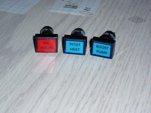
When you cut out the face-plate, leave some tabs onthe ends to mount it to the panel. I don't have any "in-process" pictures of the project, but here is a finished one which should really give you enough info to go "Ahah! So that's what he did!"

Let's see, what else? The panel mounts with a couple of brass 4-40 screws through the tabs on the ends. Leave similar tabs on the LED holder, and the whole thing sandwiches the panel and makes for a nice easy mount. I used different color LED's because my local source had them, but you can use all white, and simply control your color with the background of your label. You can argue all day about what to annunciate, and what the colors should be - I'll just refer you to multiple studies on cockpit design, and I am sue that you can find at least one scholarly reference to support just about anything you want to do! hey, it's YOUR panel, do what you want!
(I am fortunate to have a local place called the Electronic Parts Outlet that sells a mix of new and surplus components. I can spend hours (and lots of dollars) rummaging through their bins to find stuff to tinker with. If you have to settle for Radio Shack, you CAN get everything there, and the values I gave are a good starting point. )
Have fun tinkering - it's the part of homebuilding that makes it fun for me!
Paul
I am not sure what precipitated it, but in the past three days, I've gotten five emails from people wanting to know about the annunciator panel in my RV-8. It sits just above the top of my two GRT EFIS screens,and fits the dimensions of the stack.
Naturally, I was incredibly lucky to find something that fit the design so perfectly....not!
In truth, this was a little project that took me one evening to prototype, and another day to build the flight unit. You have to have something to do when the empennage is sitting there finished, and you're waiting on a QB delivery!
I knew from the very start of my panel design that I wanted annunciator lights - some to wake me up to warning conditions (Oil Pressure, EIS alarms), and others to wake me up that I'd left something turnd on (fuel pump, pitot heat, etc.). I am used to having both raw data and "idiot lights", and I saw no reason to change what worked. After looking through lots of catalogs, I didn't find anything that I really liked (or that I liked and could afford), and realized that all I really needed was a bezel in which to mount some LED's.
In a walk through the Aviation Aluminum department of Home Depot, I found an interesting fact - they had square aluminum U-channel in sizes that "nested" inside one another. I realized that if I could cut nice square openings in the bottom of a U, I could use that as the front, and put the next smaller size in from the back as an enclosure to hold the LED's. I purchased anough material to screw up several times, and headed to the shop. It didn't take long to cut the openings and finish them using some needle files. Next, I needed a "glass" front. This was done with a piece of translucent plexiglass from the junk bin (I think it was a flourescent light cover at one time). This was cut to fit inside the U-channel. The colored labels were laid out in Microsoft Word and printed on clear inkjet label stock. fill the area with a colored background, and print your text in bold black,and they'll look nice.
The rear piece is just a bit tricky. You can easily drill a hole to mount a round LED (in a small plastic bezel) behind each label location. But you need to have dividers between each one, or the light from one will light up the whole panel. You do this with thin pieces of aluminum (scrap) glued in between LED's - you can just use a hot glue gun. I actually cut slots (with my band saw) in the rear piece to hold each divider - a bit finicky, but only took a few minutes.
The electrical design is very simple. I "control" each LED with a +12V signal from whatever is being annunciated. (You might have to invert some sensors using a relay, but this is easily figured out). You need a dropping resistor in series with each LED - about 700 Ohms works great. I tied all of the ground sides together into a common ground, and fed this through a 500 Ohm Pot as a dimmer for the whole annunciator. You can experiment with values, and might find you want 1000 Ohms as maximum dim. It will depend on the LED's you get. I am using "superbrite" LED's - little bitty ones are too dim once you put them behind a label.
When you cut out the face-plate, leave some tabs onthe ends to mount it to the panel. I don't have any "in-process" pictures of the project, but here is a finished one which should really give you enough info to go "Ahah! So that's what he did!"
Let's see, what else? The panel mounts with a couple of brass 4-40 screws through the tabs on the ends. Leave similar tabs on the LED holder, and the whole thing sandwiches the panel and makes for a nice easy mount. I used different color LED's because my local source had them, but you can use all white, and simply control your color with the background of your label. You can argue all day about what to annunciate, and what the colors should be - I'll just refer you to multiple studies on cockpit design, and I am sue that you can find at least one scholarly reference to support just about anything you want to do!
hey, it's YOUR panel, do what you want!(I am fortunate to have a local place called the Electronic Parts Outlet that sells a mix of new and surplus components. I can spend hours (and lots of dollars) rummaging through their bins to find stuff to tinker with. If you have to settle for Radio Shack, you CAN get everything there, and the values I gave are a good starting point. )
Have fun tinkering - it's the part of homebuilding that makes it fun for me!
Paul