What's new
Van's Air Force

Don't miss anything! Register now for full access to the definitive RV support community.

Can APRS antenna impact comm antenna?

Ron Lee

Well Known Member
In anticipation of finally procuring an APRS unit, and given that the MT-TT4 is not available in a 1 gigawatt unit yet, I will probably install a SB* antenna on the bottom of the fuselage somewhere near the comm antenna.

Is there a potential for interference between these two systems?


* Sam Buchanan
 
Is there a potential for interference between these two systems?

I don't think so (though still a good idea to put them as far apart as easily possible). My rationale:
  • The APRS antenna is very short duty cycle (100ms every minute?).
  • The APRS signal is FM modulated (with a pretty narrow band) - your av radios are AM
  • The 144.39 APRS freq is far away from your av radio freqs.
 
No issues with Wingtip Antennas

Ron,

I have not heard any noise with the wingtip J-pole - I think Sam's belly mount has been clean, too.
 
Ron,

I have not heard any noise with the wingtip J-pole - I think Sam's belly mount has been clean, too.

Yep, I have a clean belly...:eek:
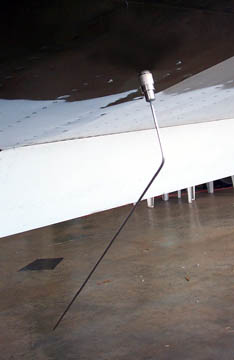
....but the comm antenna is on top of the turtle deck. However, we have a couple of local RVs with comm and aprs antennae on the belly and they are working fine.
 
I have a homebuilt APRS antenna 2' from 2 separate belly COM antennas. I heard no noises at all.
 
Antennae issues

Two antenna in proximity to each other are very likely to effect to some degree the directionality of one or both antennas, both in receiving and in transmitting. I think its unlikely that you will have interference per se between an APRS transmitter and your Com unit. By the way Sam, the 10 Watt prototype amplifier for the TT4 is working well on my workbench. Not quite a Gigawatt, but then again, you don't need Mr. Fusion to run it.....

Allen
VHS

Two antennas within a wavelength can produce a high vswr (Not Good) on either one whether transmitting or receiving. Try to get them as far apart as possible from each other.

I have seen transmitting vswr go from 1.5 to 1 to 10 to 1 when an antenna or other obstruction is placed close to the transmitting antenna.

This is from my old CB Radio days. Maybe some of the Extra Class Hams can chime in on this.
 
Gigawatt APRS unit

I really don't need that much output power. I have noticed extended coverage gaps on Rick's unit coming back from Page AZ (to Colorado). Hence my current plan for a belly antenna. Supposedly mo better transmission.

More power within reason is certainly desirable..if only a watt or two. I fly in desolate areas.

One wavelength separation is 19 inches times four. I don't think I can manage that. At least I don't want to run coax that far back but I need to think about it.

You will see a lot of RV's with two com antennae on the belly of the plane within 1/4-1/2 wavelength of each other. While this may theoretically cause some issues, it doesn't appear to be a problem in actual use.
 
Good point Sam

I suppose I can install the SB APRS antenna up front and change it if it causes problems.

I do have a question about your connectors and the recommendation to use another type...maybe it was TNC (may be wrong). Is your setup working fine? Ok, it was a possible 3 dB loss using your type connector.
 
3dB?

I don't have the figures handy, but I think we're talking a couple of tenths of a dB. 3dB would be half of the signal lost. Most manufacturers use the PL-259/SO-239 connection for ham 2M gear. A BNC or TNC will perform better, especially at higher frequencies, but the main advantage I see is smaller size.

Paige
 
I suppose I can install the SB APRS antenna up front and change it if it causes problems.

I do have a question about your connectors and the recommendation to use another type...maybe it was TNC (may be wrong). Is your setup working fine? Ok, it was a possible 3 dB loss using your type connector.

I don't have the figures handy, but I think we're talking a couple of tenths of a dB. 3dB would be half of the signal lost. Most manufacturers use the PL-259/SO-239 connection for ham 2M gear. A BNC or TNC will perform better, especially at higher frequencies, but the main advantage I see is smaller size.

Paige

Looks like Paige has this covered.

The home-brew antenna is performing very nicely. The only issue related to the APRS installation I've noticed is some RF leaking into the avionics when a beacon is popped. The CHT on my engine monitor will bounce for a couple of seconds when the tracker fires. This could be due to the tracker being located up behind the panel in close proximity to the avionics, but it is more likely due to the coax termination at the antenna reflecting RF back up the coax. I have the coax soldered to the SO-239 bulkhead connector--a more elegant installation would be a bulkhead connector that would accept a PL-259 on both ends. This would no doubt be less likely to leak RF, but I couldn't find such a connector locally so went with the SO-239.

tracker-20.jpg


SO-239/PL-259 connectors were used with the home-made antenna in order to accommodate the 1/8" stainless welding rod element. I was also concerned about how a BNC would tolerate the weight of an antenna element in the harsh slipstream on the belly of the plane.

tracker-5.jpg


Next condition inspection when the seat pans are opened up I will try winding any excess coax at the antenna into a tight coil to create a choke that may prevent reflected RF.

Perhaps the best external whip would be a conventional COM whip antenna that has the BNC connector. It could be trimmed slightly to bring it into resonance with 144.39 but I've heard of at least one APRS installation with an untrimmed COM antenna that is working fine. The tracker can handle SWR up to 20:1 so there is no danger in damaging the transmitter if there is a slight mismatch with the antenna.

I still think the external antenna is definitely worth the effort if you want to squeeze max performance from an APRS tracker.
 
Last edited:
"I still think the external antenna is definitely worth the effort if you want to squeeze max performance from an APRS tracker."

What he said....

Allen
VHS
 
Hey!

You guys must be members of the "Anti-Jpole Antenna Haters Club"!!

While I really like the subtle elegance of the hidden antenna, I agree that the external whip is the way to go for max APRS performance.

If my flying backyard looked like Ron's, I'd probably install a whip.
 
You guys must be members of the "Anti-Jpole Antenna Haters Club"!!

While I really like the subtle elegance of the hidden antenna, I agree that the external whip is the way to go for max APRS performance.

If my flying backyard looked like Ron's, I'd probably install a whip.

Yep Pete, that's the ironic part of this deal. My area of the country is so populated with iGates I could probably use a worn out cleco for an antenna for local flying and still get on the network..... ;)

The J-pole obviously works great for most users.
 
install pics for aprs

Can y'all list any good builder sites showing off the APRS installation? Color me curious.

Don
 
Not much to it.....

Can y'all list any good builder sites showing off the APRS installation? Color me curious.

Don

Don,

You won't find very many detailed install pages because the APRS installation is so simple. The system is just the tracker, an antenna, and either a hockeypuck GPS or GPS data feed from an existing GPS receiver. It really doesn't matter how you "install" the tracker, just make the connections and you have it. Deciding on an antenna is the biggest part of the installation.

Here are notes on my site about my tracker installation:

http://thervjournal.com/tracker.htm

I assume you have read the stickies in this forum:

http://www.vansairforce.com/community/showthread.php?t=27680

http://www.vansairforce.com/community/showthread.php?t=27773

http://www.vansairforce.com/community/showthread.php?t=26797

Feel free to ask specific questions you have about APRS. We can either direct you to info already published here or provide answers to your questions.
 
Last edited:
aprs requirements

Neat. So this looks very much self-contained and inexpensive. If I want to add APRS, I should be able to install the complete system in a wingtip.

Since it only uses 6.6mA, it seems like I should also be able to use an existing power line source, such as strobes. (Obviously power-in to the strobe power supply). So turning on/off strobes would be decent time to start position reporting.

Now just gotta see about studying for the HAM test....

It'd be really neat if one could receive weather data from the ground and emulate the XM-WX serial output.
 
Last edited:
Neat. So this looks very much self-contained and inexpensive. If I want to add APRS, I should be able to install the complete system in a wingtip.

Since it only uses 6.6mA, it seems like I should also be able to use an existing power line source, such as strobes. (Obviously power-in to the strobe power supply). So turning on/off strobes would be decent time to start position reporting.

Now just gotta see about studying for the HAM test....

It'd be really neat if one could receive weather data from the ground and emulate the XM-WX serial output.


What did I miss there? What draws 6.6 mA?

Allen
VHS
 
Coverage gap

If you look here: http://aprs.fi/?call=KA4HRD

On 13 April 2008 the coverage around the Four Corners area is excellent. The same basic path on 14 April has a gap of about 25 minutes and marginal coverage for a slightly longer period in the same area.

That is hardly acceptable. Rick was using a 300 mW unit and a temporary antenna setup. I am not sure what the issue was or whether more power or a belly mounted antenna will solve the coverage problem.
 
Since it only uses 6.6mA, it seems like I should also be able to use an existing power line source, such as strobes. .

Don - I think the tracker draw is a few amps for a short period per cycle. I power them off my LED Nav light circuit.
 
power

Ah, Sorry, I was reading about the wrong device (TinyTrak instead of MicroTrak) on the byonics website.

Looks like the power rqmt for the system is just under 400mA, with 180 of that being burst.

From the microtrak guide...

"Because of its small size and light weight, the MT-300
Version 1.5 is ideal for portable and airborne
operations. Small size not withstanding, the Micro-Trak
300 has a power output in the range of 300 mW, and is
capable of operating at extremely long ranges. An on-
board 5 volt regulator provides an optional 200 MA,
power output for your GPS receiver. (Many
applications, including the use of the device with hand-
held GPS units, will not require the 5 volt output of the
Micro-Track.) The entire system runs well on 9-15 volts
DC, and draws only about 10 milliamps in standby, and
increases to 180 milliamps during transmissions (which
last approximately 1/3 of a second using MIC-E)"
 
Current draw

The Micro-Trak 300 only draws a few milliamps when its waiting to send signals, most of which is eaten up by the Green LED that indicates the unit is receiving valid GPS data. It draws about 180 mA when transmitting , typically for about 300 ms when you use MIC-E. If you are powering a GPS through the Micro-Trak's DB-9 port, it adds about 60-80 mA continuously to the total draw. This gives an ambient draw with a GPS of about 80 mA, a peak draw of about 260 mA. Still, almost inconsequentially small.

Please remember that the MT-300 has been discontinued. I built a small run to meet the needs of you guys and a few high altitude balloon operators. when they are gone, they are gone. The other models are still current.

Allen
VHS
 
Back
Top