What's new
Van's Air Force

Don't miss anything! Register now for full access to the definitive RV support community.

Grand Rapids EIS-4000 retrofit

Bubblehead

Well Known Member
As long as I'm working through retrofittting an EIS-4000 in my RV-8 I thought I'd put some notes in a thread. Hopefully it will help others.

As background, in October, the 180 hp IO-360 engine in my RV lost considerable power on takeoff but a safe return to the home airport was made. Compression checks were depressing, and it turned out three of four cylinders had gone south. Perhaps "toes up" is a better term. It's 24 degrees outside so "going south" sounds pretty good. The fourth cylinder was not in too good of shape either so after reading postings on VAF, talking to friends and knowledgeable A&Ps I decided to order 4 new ECI experimental cylinders with 9:1 compression ratio pistons.

Of course, one thing lead to another. The front oil seal was leaking so we pulled that out and will install a new one, the original cylinder baffle system was pretty kludged up so a new one was ordered from Vans, and the magnetos had 500+ hours on them, so off they went for a checkup, followed by a big check. A few other things were found like 2 loose screws on the starter solenoid and a missing nut on the starter.

One thing I realized when the engine lost power on takeoff and while I headed back for the safety of the runway is that my engine instrumentation was adequate but could be better. Perhaps a better system could have predicted the problems with the cylinders so that a potential emergency landing could have been avoided. The plane has the standard Vans instrumentation - oil pressure, oil temperature, voltmeter, with CHT and EGT selector switches to monitor different cylinders. THe tachometer was a cable driven type and manifold pressure was monitored by a bourdon tube style instrument instead of the electronic version Vans sells now.

The major problem was having to switch between cylinders. I got lazy. Once I found the hotest cylinder I kept the switches on that cylinder and rarely if ever monitored the other cylinders. It was tough to spot changes and to do a good job at leaning too. The end result is problems on the three failing cylinders were not noticed until they caused a significant loss of power.

My bank account took a major hit on the cylinders (about $4k) and the magneto ($800) so going to even a low cost a EMS like Dynons was not a realistic approach. I ended up buying a EIS-4000 from Grand Rapids Technology through SteinAir. Have you guys heard of them? :p

Now that you have the background, on following posts I'll give some info on the retrofit.
 
Out with the old

After about 6 hours of work I now have the following instruments out of the panel:

oil temp and pressure
CHT and EGT and selector switches
Tach and Manifold Pressure gage

That seems like a long time for just those six instruments but I also started removing some of the old wiring. I bought my RV already flying, so whenever I tackle wiring problems it takes longer because I have to track and trace and follow wires as they twist and turn through the plane. Most of the wiring was done pretty nicely but not on these gages. It was a bit of a rats nest behind the panel. The last two hours today was spent trying to separate the wires for these 6 gages from wires to the radios and the electic T&B.

Once I got things untangled I stopped because I did not know how I wanted to proceed. I can track the wires through the instrument stack, across the radio stack and toward the right gear tower. From there I'm confused. Some of the wires are probably power from the switch panel and some are probably signal wires from oil pressure, oil temperature and fuel pressure sensors, but how they split and head in their respective directions I'm not sure! There's an even bigger rats nest at the right gear tower and I'm not sure I want to try and untangle it.

Talk about a can of worms!

So, there are two paths forward.

1) cut off the excess wire, tape or shrink wrap the ends and tie-wrap it up behind the panel where it can never do any harm.

2) keep unraveling the other mess until I can remove all the now-unnecessary wires.

I want to do option 2 but I was getting tired and found myself trying to talk myself into option 1, so I extricated myself from under the panel and worked on putitng tools away, picking up the trash, and bagging screws from the gages.

Then I went home.

I'm on vacation Monday and Wednesday (big customer coming in Tuesday) and am off Thursday and Friday so will keep plugging away. Thursday is family, turkey and football but I should make a lot of progress by Saturday night. My buddy Brad (A&P/AI) is coming by Wednesday night to help put the new cylinders on. I will sure be glad to get the engine closed up again.

I'll keep posting as this progresses. I'd welcome any suggestions or words of wisdom anyone might want to share. My wife says I'm pretty good at ignoring suggestions, and I think I have plenty of wisdom already, but what the heck, post anyway! Like the song says "just leave a number, maybe I'll call!"
 
Words of Wisdom? Keep plugging away, and let it takes the time that it takes to get it cleaned up. You can go back and find the thread on the panel upgrade that we did to "Mikey" last year - started a year ago this week, and finished up at Christmas. Getting all the old wires out was easier for us, because we were trashing the entire panel - but you can do it as well.

Since at least some of the wires you are trying to replace are going FWF, you can do a little tugging at the engine end, and see if they come out at all. Figure out where they penetrate the firewall, and you'll have a good idea where they go. Also....remove the forward baggage compartment floor - this will give you a lot of insite into the wires going forward, and is a lot easier than working through the cockpit.

And you already figured out the most important thing - walk away when you get frustrated and are ready to cut corners.

Paul
 
good on ya

I second Paul's words of wisdom. Good on ya for going home. It makes the job take longer but it will be done right.
Maintenance is never something that should be done in a hurry.
As for the wires, I just "finished" installing the harness for a GRT EIS 4000 in a friends plane and found the instructions helpful and diagrams are furnished for the aux inputs like fuel pressure, OAT, manifold pressure and fuel flow as well. Have not powered up the unit yet but all the wires are connected.
Had to remove all the wires in the plane not just the ones for the old engine gauges. The plane is getting a new panel as well as a new electrical system. It had lots of wires running every which way and no labelling anywhere. I have felt your frustration.
The wires for the EIS are all color coded. That should help when you get it in there and routed. Of course that does not help getting the old wires out.
The way I found to do it was to go one wire at a time.
After you have routed a wire and connected it highlight it on the drawing. The avionics techs I work with do this on the drawings for radio systems, seems to work for them.
Good luck
Phil
 
Paul - I can always count on you for support and wisdom. I have read your thread on Mikey's upgrade. It may be one reason I decided I should tackle this. By nature I am a "work until it's done or you drop dead" kind of guy, but learned long ago that I achieve better results if I break a difficult task into manageable pieces and quit when I get frustrated. I needed to hear the reinforcement though.

Great idea to remove the floor of the baggage compartment. I will do that today. I wish the builder had put the access door into the baggage compartment rear bulkhead but I'll have to work around that.

I have everything disconnected forward of the firewall and have done the push-pull thing. Wires on the port - er, left side of the plane go through the baggage compartment above the floor so I have pretty good access there. It looks like there is enough room through the grommets for all the EGT/CHT wires to go down that side. If possible I will route OT, OP, FP wires that way too. Then all I need to do on the starbord - oop - right side is remove wires. That should straighten a lot of things out in the remaining rats nest.

It looks like I can mount the MAP sensor about the same place as you did on your -8. My encoder is there too but plenty of room for the sensor.

I like your idea of highlighting wires as you run them. I will make a copy of the diagram from GRT to mark up during the process.

AME at large - thanks for the positive reinforcement. Weather's bad anyway so I might as well be upgrading. So far it seems like the instructions and diagrams from GRT are pretty good, despite some gramatical errors.

Here's another question. It appears that all the instruments receive power through one circuit breaker on the aux panel as diagramed on Vans generic diagram. However, instead of running one wire from the breaker to the instrument area and then "daisy chaining" the instrument supply side, he ran individual wires to each instrument. That may be why I have such a rat's nest around the right gear tower. I realize that would make it less likely that I would loose power to all engine instruments, but it sure makes for more complicated wiring.

Any suggestions on the right way? Obviously with the EIS-4000 I will only need one power wire from the breaker to the EIS and all redundant wires can come out, but just for general knowledge what is the better way to wie a series of instruments? I may post this question on the "Aeroelectric List" too.
 
Day three - more cans of worms

So when we left our intrepid dabbler he had gotten good advice from a couple other convicted dabblers, so off to the hanger he went.

After a quick stop for catnip (for the cats) and Menards (for a jig saw for cutting the panel) and OfficeMax (for lables for the labeler - they did not have the right ones) I arrived at the hanger ready for action. Step 1 - remove the forward baggage compartment floor. As with every other operation on this RV, it was not as easy as it should have been. Most screws in this plane have a little or a lot of head damage so getting tight screws out is difficult even when I can get at them. As you all well know, most screws in these things are positioned such that a normal sized screwdriver cannot be used. Also, unless a tap is run into a nutplate the screws ater tight! The screws on this floor were no exception.

Most of them came out fine except the ones along the far side of the fuselage. One came out fine, one was missing (yeah), one started coming out and was worked out using a pair of vice grips, and the last one barely budged before stripping the head. Vice grips could not get a grip (and I was starting to loose mine) but my air driven cutting disk came to the rescue. I was able to grind off the head of the screw and lift the floor out. Tomorrow I'll run a tap into all the nutplates I can get to and the installation and the next removal will go better. I'll also replace all these screws with socket head screws like I've done on most of the interior panels. I'll also use a little wax from a toilet ring to lubricate the threads.

Ironflight was right - removing the floor helped a lot. Of course as I looked down into the brake pedal area I decided the opening looked suspiciously like an open can of worms. Except dirtier! I also noticed there were a couple of bubbles in the brake supply lines. Of course, I could not get the bubbles moved up to the reservoir without loosening one, then the other Adel clamps, then snipping some tie-wraps then removing some spiral wrap!

Even then things were not exactly right, so I decided to take one of the lines off at one end to reroute it. That's when the brake fluid ran down the cockpit floor!! I finally got the lines back into place and hooked back up and cleaned up the cockpit floor, followed closely by adding a note to my project "to do" list to top off the brake reservoir before closing up the cowling!

OK, so I started out to work on wiring today and just spent about 2 hours on the floor and the brake system! Oh yeah, the other good thing about having the floor out is it is so much easier to get good lighting in there! That made it worthwhile.

So, back under the panel to work on pulling out some more of the old wiring from the engine instruments. I brought a smaller side-cutter with me from home this time and could get at many but not all of the cable ties holding the wiring together. I kept working at the next one and the next until only one was left - directly behind the radio stack! Out came the radios and just for good measure, the intercom too. Still can't get at the cable tie but I see all it's holding is some excess cable so with a light tug, the 2 EGT cables and 2 CHT cables of the left side cylinders are loose! A few minuters later they are completely out fo the airplane and laying on the hanger floor. Some success! It sure felt good.

More in the next post.
 
Now for the right side EGT CHT wires

So back under the panel and there was just no way to get at the cable ties that bundled up the EGT and CHT wires along with power and oil temp and pressure signal wires that go up the right side of the plane. It looked like if I could just slide the panel out a little I could get room to manouver and get things sorted out. All the panel screws came out easily, but the panel wouldn't move. Oh, I forgot the two screws from the radio rack to the airframe needed to come out. Then the vacuum lines held things up. Back to the baggage compartment where they come through so I could take them loose from the regulator.

Back into the cockpit and the panel slid out aways and yes, I could get at the rest of the cable ties. Snip, snip, snip and the remaining wires came (mostly) loose. I slid the panel back in place and put a couple of screws back in to hold it in place until I am ready to button it back up.

The EGT and CHT wires pulled out fine, so now 8 pairs or wires are now laying on the hanger floor. And that is when I got to the stopping point. I laid there for about 15 minutes looking at lots of wires coming out of the right side tower going every possible direction. I really don't know where the guy who wired this thing learned to wire. There are only a few loads left after all these engine gages are out, but there are 20 or 30 wires in one little area!

There is one other thing that I need to figure out under the panel. Above the right side tower there are three terminal strips with lots of ring-terminaled wires attached. Each terminal strip is set up like a buss with a copper "buss bar" connecting one side of the terminals. Over the top of these is a plexiglass shield. Tomorrow may be voltmeter time. I'm thinking of removing the plexiglass shield and trying to find out which circuits on the right side panel are connected to which buss bar under the plexiglass.

So far this project has consisted of taking a lot of things apart and nothing going back together. My engine is missing cylinders, prop, front shaft seal, exhaust, intake, baffles, and oil cooler. My panel is mostly out of the plane except for the 6 flight instruments. I even had to take the compass out to get at some wires! Seat backs are out, cushions are out, the PTT on the back seat stick is broken, and wires are hanging loose under the panel. There's no going back to the old world, Sven just burned the boat!

I wish I could bring myself to get the EFIS so I could pull out the flight instruments and vacuum system. Yes I'll have a couple of backup instruments but not vacuum. I just don't want to give up the cash right now. Maybe next year!
 
Grand Rapids

Bubblehead:

I see that you're still running about half a bubble off!;) (This is an old Submariners term, btw). See if you can find one of the small side cutters that are used for nipping the leads off electrical components soldered to circuit boards. They nip the nylon zip ties off so close to the grip side that you'll never get your hands or arms cut by one of the zip ties again. They're really good also at cutting off old zip ties without knicking the wires that you're trying to free up.

I went through this recently when I installed the GRT Sport along with the EIS 4000. Take your time. Electrical installation is an easy process! There are only two ends to a wire!:D
 
play by play...

Thanks for the running play by play as you dig deeper into the wiring of your -8. It's helpful to hear all the behind the scenes stuff that is usually ignored or not mentioned when people talk about panel upgrades and modifications.
As a "convicted dabbler" I may be able to offer some info.
There are many ways to wire a plane let alone a series of instruments, I would say just make sure they are wired in parallel and not in series if doing so. I would have a fuse or breaker for each one but with six or seven gauges that takes up a bit of space.
Tight screws in tight spaces are a pain. I would not run a tap into any nutplates as it can reduce the locking feature. Instead I use a small dab of grease on the threads and that lubricates the nutplate and reduces friction. Not so much that the nutplate does not lock but enough to make sure after a few hundred flight hours that the screw will come out. Wax would work as well I think although I have not tried it.
This is important when using stainless steel screws as they are fantastic at galling and destroying the threads in the all metal locking nutplates. It's helpful to prevent corrosion as well. Because of the corrosive environments we fly our planes in its standard procedure to lubricate all nutplates and fasteners. We do it not so they go in easier but so they will come back out at the next inspection without needing any special tools or having to be drilled out which takes longer/costs more, etc...
I have used valve grinding compund on the tip of my screwdriver to help loosen stuck screws. It provides enough bite that a tight screw will loosen without stripping.
A good pair of flush cutters makes quick work of tywraps. Even a cheap pair from an electronics store is helpful for cutting those suckers off, they are thinner than side cutters and narrower in the tip as well. Good for tight spots.
The EIS wiring is long enough and some of the probes have long enough wires that splicing for extra length is not required. I have a few photos I can Email you if you like. As well I took the suggestion of another poster here and used Express SCH to draw system diagrams for the electrical system I put together. I can send you the drawing I made for the EIS as it has both connectors and Aux. inputs on one page. It's not as complicated as the multiple pages that come with the instrument make it out to be.
The plane I'm working on is a Cavalier and has about the same layout as a RV-6. The wires for CHT and EGT were long enough from the instrument to reach the engine with length to spare. All EIS wires are run through the same hole in the firewall on this plane. It looks like a lot on the drawing but once you go through it and pull out the wires you aren't using the bundle gets quite a bit smaller. This plane only has two Aux. inputs and no carb. temp as it's fuel injected to there goes half a dozen wires right there.
About those terminal strips, are they used to run wires for cockpit lighting?? Or are they for load distribution??
Thanks for posting your progress. Hope this helps.
Phil
 
Bubblehead:

See if you can find one of the small side cutters that are used for nipping the leads off electrical components soldered to circuit boards. They nip the nylon zip ties off so close to the grip side that you'll never get your hands or arms cut by one of the zip ties again. They're really good also at cutting off old zip ties without knicking the wires that you're trying to free up.

Or you can take an old set of side cutters and with your belt sander, sand the back side till the taper of the cutting edge is gone. Then it will work as above.
 
Phil,

Thanks for the thorough feedback. Lots of good ideas there.

I tried the tap in the nutplate thing a year ago during the condition inspection. I don't go very far in, so while the screw starts easier the nutplate still grips fine. All my interior panels are now done and none of the screws have loosened in the last year and 100 hours of flying. I'm using zinc plated socket-head screws so corrosion should not be a problem.

Thanks for the tip on flush cutters and valve grinding compound. Both would have come in handy yesterday. I'll pick some up today.

Thanks for the good info on the EIS wiring. I would appreciate a copy of the schematics. I too am using ExpressSCH so having the document would be very helpful. I'm hoping to do like you did on the Cavalier. Run all the wires for CHT and EGT as well as other engine side sensors through one hole in the firewall.

That's a good question about the terminal strips. Cockpit lighting is non-existent on this plane, and only two instruments are lighted. That's another reason I'm looking forward to installing an EFIS. I'll take a picture of the terminal strips tomorrow and post it just as a point of interest. I just cannot imagine what all the wires are for.

I have to work today but am off through the weekend so will be back at the hanger Wednesday. I'll pot again then.
 
wiring woes but light at the end of the tunnel

This project has been one of those where every step of the way more work presented itself. As I started pulling old CHT and EGT wires I came across several wiring areas which were mediocre at best. A couple of days ago I uncovered a rats nest around three terminal blocks and some key wires to the alternator running over two raw metal edges.

It's taken a couple of days to unravel some of the mess, but today I was able to finally get at some cable clamps keeping the wiring tight over the raw edges. I now have enough slack in the right area so I can add plastic edging over those raw edges so the wiring will not chafe and unltimately fail.

Now that I got to that point I can see a better route for the wires so I need to take even more things apart before I can put them back together. It means probably not having this back together until Christmas or even New Years. But when it is done I will have a lot more confidence in the plane. Even after this work is done there will be more re-wiring to do, but at least I've bought some time before doing that. Perhaps next Thanskgiving.

As I get past the rewiring portion and back to the installation of the EIS I'll start posting again in this thread. I have some other electrical questions I'll post elsewhere.
 
Progress!

I made some good progress in straightening out the wiring mess today. I finally figured out what wires went where and what the three terminal stips on the right gear tower are for. Once I understood that I felt safe pulling out the Fuel Pressure and Voltage gauges and their wires.

All the old gauges are out except the fuel level gauges. I removed the last of the wires from engine compartment sensors (OT, OP, FP) and voltage as well as the ground wires for each instrument.

The next step is to reroute the ignition and alternator wires so they avoid the two sharp edges of their old route, and to put edge protection around the top hole of the right gear tower to protect the bundle of wires that come through it.

Next weekend I hope to have all the rewiring done so I can get back to work on the EIS installation.
 
if it's not one thing...

....then it's another. I know just what you mean when you describe getting into that wiring and not being able to do the job you had planned. It's frustrating but a better airplane is the end result.
The EIS wiring will go quickly, the programming of the instrument may take a while. I have yet to power up the unit I'm working on as the panel is still on the bench so I can't comment on that part.
Now you know your airplane better than you thought you did and I'll bet more than you wanted to as well. It's important to get to know what is hiding in the nooks and crevices and become familiar with an airplane that you didn't build. This builds confidence in it as you have said.
It will fly again, when it's ready.
Phil
 
finally some progress

The last couple of months have been tough. In December business at the other division of the company I worked for tanked! Business dropped about 80%. Even though my division was still profitable there were big layoffs in December and again in late January. I was one of those who's position was "eliminated."

So for the last two months most of my time has been spent trying to find another job through networking, recruiters, checking corporate websites and checking every job board I could find including Monster and Career Builder. So far no luck but in the last two weeks I applied for several jobs that I felt were a good fit for me and the hiring company. No word back yet though!

So we shift to plan B - finish the EIS installation and then off to Sun-N-Fun to see if I can sell the -8. I really hate to do it because I love it and have upgraded a lot of things including tailwheel, fuel valve, 4-into-1 exhaust, improved cabin heat, new ECi cylinders and the EIS-4000. I'm just getting it like I want it and may have to sell to conserve cash. Maybe I can find a partner in the Chicago area.

Anyway I am back on the EIS installation. The panel has been cut to accept the unit, the wiring harnesses are labled and one (EGT/CHT wires) has been run to the engine compartment. All the old gages are out and tomorrow I start wiring all the other data channels.

I am installing the Hall-effect sensor and wondered where and how people have mounted it. I plan on putting it on the alternator output in the engine compartment, perhaps attaching it to one of the members of the motor mount. I'd appreciate any advice especially pictures.

The other thing that is confusing me is I was tracking wires around and found that one of the two small wires that go to the alternator is connected to "instrument power." I will track down the other one tomorrow and hope it goes to the alternator field breaker on the electrical panel.

Why would that wire come from the instrument power bus? The alternator is the old Nippondenso 821663. Does anyone have a wiring diagram for that unit? The generic Vans diagram that came with the plane shows a separate regulator. Here's a couple of pictures.


On the topic of sidecutters, there is one product on the market that leaves everything else in the dust. Not cheap, but absolutely superlative for any task associated with aircraft wiring (except cutting BIG wire).

Snap-On Part Number E710BCG sidecutters.

Got my first pair about 22 years ago. They worked fine up until a year ago when my daughter used them to cut hardened jewellery wire. She's since replaced them and now understands just how expensive GOOD tools are, and which tools in my toolbox she'd better not touch on pain of death! ;-)

My second pair were picked up from the Snap-On dealer (Steve Garrow) at Oskosh last summer. Total price including taxes was $48.15 with the 15% EAA discount applied.

These are large (6") flush-cutting sidecutters with spring return. They'll cut wire, tie wraps and do a find job on lacing cord, too. I normally wouldn't recommend spending the big $$ demanded by Snap-On, but in this case the tool is so good that it's worth every penny.
 
Hall Effect

Here is how I mounted mine:

amp%20sensor.JPG


Wiring diagram is shown below:

engine.jpg


Another shot: http://picasaweb.google.com/tc1234c/GRTInstallation#5059703491720688322
 
Last edited:
Ted - thanks for the diagram and the link. The pictures were very helpful. It looks like you are measuring Battery amps charge/discharge. I have read all the comments pro and con and will probably go with putting it on the alternator output. Each way has strengths.

The picture of the hall effect sensor was very helpful, but it looks like you have wrapped the cable through twice. Is that true, and if so, does that cause the reading to be 2X the actual current?
 
current sensor

Hey John

Good to hear that the installation is going well, looks like many of your questions have been answered. Hope the job situation works out for you.
Wrapping the wire twice through the unit is in the instructions;

"For sensing -50 to +50 amps; Loop the wire which carries current being sensed through the sensor so that it passes through it two times"

Not sure what that does but it makes the max reading only 50 amps instead of 100. If you wrap the wire ten times through the sensor it reads only +- 10 amps. I'm sure there is an explanation, perhaps Paul can help out here....
Good luck
Phil
AME at Large
 
Phil is right. I am sensing -50 to +50 amp, so the 2 loops. Of course the scale factor and offset have to be changed to. Since at lower current the signal is weaker, by looping the cable you increase the signal that get picked up.
 
Phil and Ted - it makes sense! Since I'm setting up mine for a 60 amp alternator I did not read closely the 50 amp setup.

Thanks for the amplification. There's always a lot of good info shared on the forums.
 
Last edited:
Great progress today

I'll post some pictures tomorrow but I made a lot of progress today. I was able to use the power and instrument lighting power wire that was used by the fuel gages for the two signal lines to the fuel senders. That saved having to try and route two wires through incredibly small openings. The new panel sans fuel gages is now in place. I also ran a new wire from the left wing root for the pitot heat. The old routing ran the power behind the panel right past the compass. Funny thing but whenever pitot heat was on I could hold a compass heading of 060 perfectly! :)

Then I finished building the terminal strip. I'll post a picture tomorrow, but
the terminal strip has the resistors for the fuel pressure and fuel level sensors soldered to the tabs, and then is used to distribute 12V, 12V Regulated, 4.8V, and all 6 aux lines. I mounted it on the back of the baggage compartment so it is accessible through the EiS mounting hole. If I get a couple of Aux lines backwards I just unscrew the EIS, slide it out and reach in to swap wires.

I also got some more of the spaghetti/wiring unraveled today and routed and tied down better. I feel really good about that although it has cost me hours of work.

Finally I mounted the manifold pressure sensor/converter to the front baggage compartment rear wall. It will be easy to route the line to the firewall connection.

Tomorrow I start the hard-core wiring from the terminal to the EIS and from the EIS to the engine compartment. If I get everything aft of the firewall finished tomorrow I will be very happy!

Sun-N-Fun starts two weeks from yesterday. I still ahve to either put the old baffling back on or install the new baffling kit I bought. The old baffling is really cobbled up but worked fine and in the interest of time I might just put that back on. I need plenty of time for test flying and trouble shooting. with the new cylinders I want at least 5 hours of time on them and hopefully 10 hours before setting off for Florida from Illinois.
 
Long day, much progress

Spent 9 am until 6:30 pm at the hanger and have almost all the wiring behind the panel for the EIS done, a lot of other wiring cleaned up, and panel lights wired. Drilled the mounting holes for the warning light and the boost pump on light. Took off all fairings and inspection covers so the local friendly AI can check things over as part of the annual.

Tomorrow I'll run the wires from the EIS to the engine compartment, wire the manifold pressure sensor and mount the EIS. Then double check all the wire runs, make sure everything is secure and cable ties are trimmed, then power up to see if the EIS lights come on.

Two other issues were decided today too.

1) oil temp - there is no way to swap the current oil temp sender for the GRT one without an engine hoist and taking motor mounts apart. For now I will reinstall the old (Vans) oil temp gage and use the exisiting sender. Sometime in the future we'll tackle the sender changeover.

2) I was going to use the tachometer encoder from Vans but will just add a toggle switch and get the tach signal off the p-leads.
 
Everything takes so ,much longer than it should!

Thursday morning I was sure I'd have everything behind the panel done. I worked until 6:30 pm and thought I'd finish it the next day. Friday had personal business to attend to, and Saturday I was at the hanger by 10 and worked until 6 pm. Still not quite done. Today I was there at noon and worked until 5 pm and still have the tach wire, fuel pressure wire and the MAP sensing line to run!

I don't know why this is taking so long. It just seems like it is taking an hour per wire! I have straightened a lot of tother wiring runs out and am trying to double check my work to avoid start-up problems, but this project is really dragging on.

Tomorrow afternoon I will get the last few things under the panel done and can start reinstalling the engine baffling. I'll have some mods to do becuase of the new ECi tapered fin cylinders but I am determined to leave for Sun-n-Fun next Monday.
 
almost done...

Sounds like you are at the 90% done and 90% to go stage.
All I can say is hang in there and I hope it all comes together for you.
I have been involved in projects that seem to drag on and on, it's depressing sometimes but you have to see the light at the end of the tunnel.
Every project has it's nasty jobs that have to be done regardless of how much you don't want to do it or how much extra time it takes.
Eyes on the prize.
Phil
 
Thanks for the verbal support, Phil. It really helps.

Yesterday was dark, windy, cold and raining but I made it to the hanger and hooked up two more wires and installed a toggle switch betweeen the tach sensing line to the EIS and the ignition switch.

This afternoon I'm heading back - it's still cold and dark but no rain - and will run the last wire (fuel pressure), finish cable tieing the bundles together, and remount the panel temporarily. Then hook up the battery and check to see if the EIS powers up or if magic smoke leaks out of anything!
 
A GREAT Day

Finally ran the last wire and the manifold pressure tubing, checked all connections, tied up the wire bundles and temporarily installed the panel. Connected the ground lead to the battery, and with Halon extinguisher in hand pulled the cb for the panel power and then flipped the master switch on and then off.

Checked for smoke or unusual smell (none found), then flipped the master on and left it on. Everything is fine! Pushed in the cb for panel power and the EIS 4000 booted up fine and the alarm light started blinking. I acknowledged all the alarms and the light changed to steady on. Perfect!

Turned everything off and checked all the wiring and connections again, finished installing the instrument panel and cleaned up the cockpit. I will leave the seats out until I get the stuff forward of the firewall hooked up and working just in case I need to get under the instrument panel again.

Next step is to reinstall the old baffles on the new ECi tapered cylinders and hook up the EGT/CHT probes along with oil pressure, oil temperature and fuel pressure. I am leaving off the fuel flow sensor for now. It's time to get flying again!
 
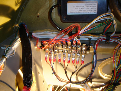
Picture of terminal block

The EIS 4000 requires a few resistors to properly excite some of the sensors like fuel level and fuel pressure, and there are three different power requirements; 12V nominal from the electrical system, 4.8V for some sensors, and regulated 12 V for the fuel flow sensor. The latst two are provided from the EIS.

I struggled with how to incorporate all this into some wiring that would be simple and would allow me to troubleshoot whatever I did wrong. Not a pessimist - just a realist! Finally I decided to use a terminal block and hard-wire the resisters in. The right 6 terminals correspond to each of the 6 aux channels. Having these on the terminal will allow me to swap channels if necessary. The left 3 terminals are all for power: 12V regulated, 12V ship's power and 4.8V excitation voltage.

It is not quite as neat and pretty as I pictured it, but it will allow me to track things down if necessary, and it made wiring a little easier. All told though, I don't know if I would do it all again. I might just splice some wires in the first 9 inches of the run from the DB-25 connector and be done with it.

513733912_rDF8r-S.jpg
 
Last edited:
The home stretch!

We're coming down the home stretch on this - finally. The EIS install was done while changing cylinders, which also ended up requiring replacement con rods and bearings and just for kicks I added higher compression pistons and a mag rebuild! The winter was the biggest obstacle of all. It is just hard for me to work in a cold, dark hanger. Even with a propane heater the cave-like atmosphere makes it a real chore!

The weather is warmer and brighter and the EIS is installed except for hooking up the final few wires in the engine compartment. The rebuilt mag should have gone on last night but the drive gear was pitted so a replacement has been ordered.

The baffles are back on and the EIS is programmed, so what remains?

1) install the mags
2) finish hooking up EGT, CHT, FP, OP, OT wires
3) install the prop and cowls
4) test run and check for leaks
5) test fly and start break-in period

I've got to be in Texas on business all next week so hopefully Saturday 5/2 we will test run the engine. All told I've lost 5 months of flying. Bad Bad Bad! I can't wait to get back in the air.
 
need info on Vans oil temp gage

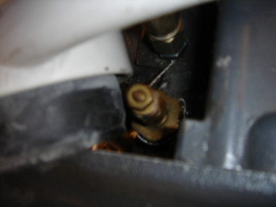
Retrofitting the EIS to a flying RV has been challenging. One challenge is the oil temp probe on the plane is the Van's probe which is not compatible with the EIS 4000's oil temp channel. The upper right motor mount prevents replacing the probe without jacking the engine and loosening or removing motor mount bolts to get clearance. Here is a (poor) picture of the sender and mount.

520396936_GX7GW-S.jpg


There are three alternative solutions.
1) use the already installed probe and mount the van's oil temp gage in the cockpit. That get's the info to the pilot and will work.

2) mount the new probe into an alternative location on the engine. Is there a secondary spot? I've looked all over the back of the engine and don't see any other likely places. Perhaps this is more of an engine question than a EIS question.

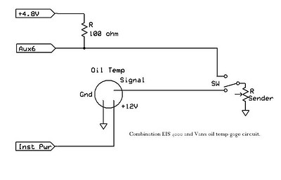
3) use the old probe along with a resister and the 4.8v source from the EIS to send the data to the remaining available Aux channel. To do this I need to develop the AuxSF and AuxOFF for the sender. I've already mounted the gage in the panel and it would be very difficult to get it out to do a voltage vs temp reading test. Does anyone have that info, or can someone develop it for me? Perhaps it can be derived by knowing the following: according to the documentation from Vans the sending unit is a 0 to 240 degree input, 33 to 240 ohm output sender.

Anyone have any ideas on either an alternative location for the GRT sender or how to figure out a voltage divider so I can use the Aux channel for Oil Temp?
 
Last edited:
I found a document on the Yahoo Group for GRT EFIS that tells how to set this up. I will look up the guy's name and post it tomorrow, but it looks like I could use a 100 ohm resistor, the 4.8V excitation voltage, AusSF=273 and AuxOFF of 373. Those seem like too large of numbers so I'll check the math in the morning and post additional info.

Now if I only had a Van's oil temp sender to test these settings with! I hate to risk overheating the oil on these calculations. Perhaps I'll use the van's gage for a while to establish oil temps with the new cylinders and then switch over to see if the numbers are consistent.
 
I think I found a way to verify the AuxSF and AuxOFF for using an aux channel with the stock van's sender for oil temp. Here's a circuit diagram of a combination Temperature Gage and EIS Aux channel using a SPDT switch. The EIS reading could easily be compared with the analog gage readings. While that's no assurance that either reading is accurate, at least I would have some confidence that the EIS is no worse than the analog gage. Once I prove that to myself the analog gage and switch could come out.

BTW the diagram was made with ExpressSch then copied to Paint, trimmed, then I used "Save As" to save it as a jpg for uploading to SmugMug where I generated the link for VAF! Sounds worse than it was!

520395659_JeZLC-S.jpg


Any comments or suggestions?
 
Last edited:
Fin Details

Since I am sensing RPM though the p-leads I need a cap to put over the tach drive output in the engine.

Does anyone know an easy place to pick one up? Do auto parts stores carry them?
 
Avery Tools

Avery Tools has the tach cap for $12.00. It's their part number 6346.

Off to the hanger to hopefully finish things up and test run late today!
 
It's always farther than you think.

When I thought I was almost done, I wasn't. The magneto drive gear had some pitting on the shaft so had to order a new one. It, along with the mag (Bendix dual Mag) were installed and the timing set Thursday night, and Friday I finished hooking up all the EGT/CHT wires, along with fuel pressure and oil temp and oil pressure sensors. Then lots of cable ties to get everything secure, finished mounting the exhaust collector, then a real good once over by a local A&P who thought it all looked good.

I might have pushed a little and test run the engine last night but wanted to get some sleep and look things over again this morning. I found more things that weren't "to code" and worked 3 hours to get them all cleared up. Torqued the landing gear bolts to finish the condition inspection and then installed cover plates. Two bolts were still at 20 ft-lbs but two others took about 1/2 a turn to get back to 20.

I had left the spark plugs out so I could spin the engine with the starter to get oil flowing, so we pulled the plane out and spun it up until I saw 8 psi on the EIS. Found one small oil leak - I had not tightened the hose to the upper fitting on the oil cooler. Installed plugs and then ... (drum roll) it started up first try! I did a 2 minute run-in and let it cool, then a couple of 5 minute runs. All the new instrumentation worked fine except two CHTs where I did not get a good crimp on the connector. Once those were replaced all 4 CHTs were reading fine.

This afternoon I finished the day with a 30 minute flight at medium power. CHTs got to the upper 300's a couple of times until I reduced power and lowered the nose a little to get more cooling. Toward the end of the flight CHTs were starting to run a little lower. Oil pressure and temperature looked really good - never saw more than about 190F on oil temp.

To top off the day I made a sweet, soft, squeek type cross wind landing. I was happy to park it for the night and go home with a big RV smile back on my face.

For the last 6 months the plane has been down for cylinders, conn rods, a couple of rockers, the EIS-4000 installation, a job loss, etc. etc. but it sure feels good tonight. I'm temporarily working in Texas next week but next Saturday I'll pull the cowling and check everything over really good and then start the break-in flights. I still need to redo the fuel tank level calibration, so will try to do that Saturday morning too. I must have done something wrong the first time. Oh, I still need to install the fuel flow sensor. I guess the work never is really done. Except tonight. I'm just going to enjoy the feeling of having a flyable airplane in the hanger again!

My thanks to everyone who offered words of support while I was working through this and to my friend Steve and his son Steven (ex RV-8 owners) who helped out with an occasional tool or a slice of pizza.
 
new cylinders and EIS flight times

Last weekend I made a 0.5 hr test flight and everything was great. Saturday I flew it for 1.2 hrs. The only squawk was the fuel levels were not reading right. I changed the sensing from + to - and recalibrated and everything is working fine now. After the 1.2 hour flight I pulled the top cowl and checked everything over. Everything was where I left it, no oil leaks found and the new wiring and sensors were all snug as a bug. I found a couple of places where another wire tie would keep things tighter and added them. After the .5 hr flight there was some oil on the belly from the vent line, which I cleaned off. After the 1.2 hour flight there was only a little bit of oil so it seems the rings are seating. The oil level only dropped 1/2 qt over the first two flights. I found a few places in the front baffling where air was probably leaking out and used some BID fiberglass and high temp RTV to plug them.

Today (Sunday) I refueled and flew from Dekalb, IL to Lewis Airport for an EAA breakfast (0.4) and then flew to Fort Madison, IA and back to DeKalb for another 2.8 hours. Once down I checked everything over again and there is very little oil on the belly and no noticeable decrease in oil level.

The only thing I am running into is once the engine heats up #1 cylinder CHT will go over 410F unles I throttle back to about 22"/2500 rpm. Oil temperature is running between 180 and 200 F. Cylinder 3 is next hottest at about 385 degrees cooler and cylinders 2 and 4 are running about 380 when #1 is at 410.

With a total time of 4.5 hours should I be concerned about Cylinder #1? I thought I might swap injector nozzles between 1 and 2 since 2 is the coolest cylinder.

I'd like to hear people's thoughts on this. This weekend I want to get to 10 hours time on the cylinders so I'll feel safe making some trips with it but would like to be able to go to higher power levels too!

Thanks,

John

PS the EAA chapter at Lewis Airport did a great job with the breakfast. There were two P-51's, a T-6, a T-28 and about 6 or 8 RVs. I'll post a VAF sighting photo when I get a chance.
 
Tach signal

John:
I have been reading your posts with great interest because I am doing the same installation in a flying RV-3.
In order to change the oil temp probe I had to remove the angle oil filter adapter. Tough to do, but done.
Can you explain about getting the tach signal directly from the P-leads. This sounds too simple. Am I missing something?

Bill Newkirk
N283RV
 
It is very simple

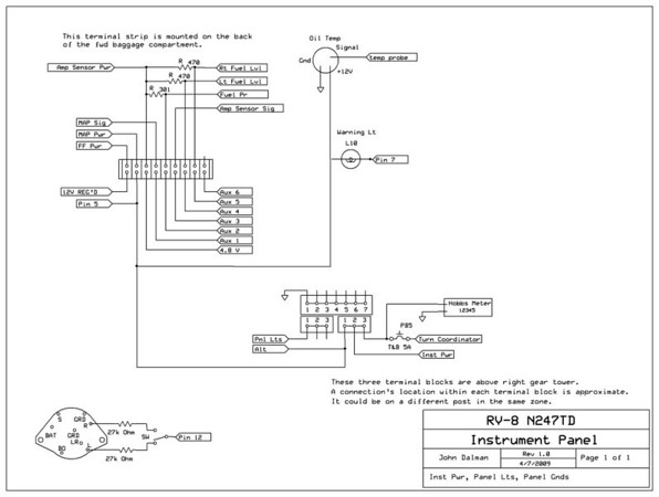
I was skeptical too, and read the instructions a lot of times. Like most other things with the EIS understanding the instructions is the hardest part. Here is the schematic that I built while installing the EIS. The lower left corner shows the tach hook up. I used a toggle switch to choose left or right mags.

You just hook the resistor and wire up to the same posts that the P-leads go to. When you do the mag check you will need to flop the toggle over once.

I'm not sure why they include two resistors though. It seems like the resistor could go between the switch and the EIS and the circuit would be functionally the same.

Let me know how it goes. BTW After 5 hrs of flying with the EIS I love it. So much better than what I had before. Here's a link to the image if you need it larger. http://tangodelta.smugmug.com/gallery/7339827_rGw7e/1/540565456_2S7Y7#540565456_2S7Y7-M-LB

540565456_2S7Y7-M.jpg
 
nice drawing

Hey John

Glad to hear that you have your RV grin back!!
Referring to the hot running cylinder, could any of the work you did to the baffles cause a change?? It does not take a big gap or leak to cause a hot running cylinder. I remember reading this in Kent Pacers fine book "Speed with Economy". I would still check the nozzles and try swapping them as you suggested.
I see you have put the Express SCH program to good use, nice work on the drawing.
Phil
 
Single Point of Failure

snipped
You just hook the resistor and wire up to the same posts that the P-leads go to. When you do the mag check you will need to flop the toggle over once.

I'm not sure why they include two resistors though. It seems like the resistor could go between the switch and the EIS and the circuit would be functionally the same.
snipped

I think the two resistors are used to prevent adding another single point of failure. If that single resistor fails or one of it's leads break, you have no tachometer at all. With two resistors, you would only lose the tach on one side of the dual magneto.
Charlie Kuss
 
Phil - the baffles are the most likely cause. I will be pulling the cowling in another 5 hours to check everything over really good. I will look for leaking areas at that time. I already found a couple like along the prop oil return line and along the tops of the cylinders. The baffle is not held really close to the cylinders along the top where it goes around the valve covers. I need to find a way to tighten that up.

It feels so good to be flying again!

Charlie - that makes sense. Since I did not know why they had two resistors I just kept faith in GRT and wired it up the way they said. I figured there was a good reason for it, and there was!
 
Tach

John;
Thanks for the reply.
Instead of connecting directly to the p-leads, I would like to retain my present Vans tach that has the generator driven by the mechanical tach drive. Sandy at GRT said it was okay to connect directly to the "S" terminal on the back of Vans tach. Hopefully this will work. Comments?

Bill Newkirk

That was the way I originally planned to do it, because I did not want to have to throw a switch during runup. I bought the unit and cable and that's when things got complicated. The cable was too long and needed to bend one way or the other or I had to find another cable, then I wasn't real happy with the mount I made. I even did what some others have successfully done, which is use cable ties or adel clamps to mount the sensor to the motor mount. I never got it secured to my liking and finally decided two days of messing with it was enough!

I put the toggle switch right above the keyed ignition switch. I had a hole there where the voltmeter had been, and I had bought a 2-1/4" instrument hole cover to plug it up. I drilled a hole in the cover, mounted the switch and wired it up. It took about 3 hours including driving to the airport.

I would still prefer not to throw a switch, but until I figure out a nice way to mount the Vans unit this will do nicely. Let me know if you need the wiring diagram for the Vans unit. If I remember right it has three wires - +12V, gnd and signal that you'll connect to the EIS.

Since your sensor is already mounted and hooked to your tach drive you've got the hard part done! Maybe you could post a picture at how it is mounted. And let me know how you like your EIS.
 
Oil Temp

I noticed today when I fired the engine, Oil Temp was 59 degrees, and stayed that way. It only ran a couple of minutes, but always showed 59 degrees. Could it be this was because the oil was not warm enough to open the Vernatherm. OR maybe there is a problem.

Bill Newkirk
 
I think the temp should have changed. What was the outside temperature? If it was not 59 then you probably have a bad connection or a short.
 
I noticed today when I fired the engine, Oil Temp was 59 degrees, and stayed that way. It only ran a couple of minutes, but always showed 59 degrees. Could it be this was because the oil was not warm enough to open the Vernatherm. OR maybe there is a problem.

Bill Newkirk

Bill,

I checked on my plane today. I am using a Vans oil temp gage not the EIS oil temp channel because I do not have the right sensor on the engine. That channel read 59 degrees today when OAT was over 70. You must have a break in the oil temp circuit. I suggest you check the wiring.

I hope it helps.

Gasman - thanks for the pictures. Nice job mounting the encoder. It gives me some good ideas how to do it if I want to change my setup.

John
 
A little farther up the learning curve

I've now flown 10 hours with the EIS and am getting pretty good at things. I recently developed some procedures to include in the POH for using the EIS including leaning functions, fuel fill etc.

Today I flew to Burlington, Iowa and back on a business trip and tried to determine if the fuel levels were showing properly. I had not gotten any degree of trust so far, although the fuel flow totalizer so far seems accurate to at least .5 gallons in 10 gallons.

On the way back from BRL I flew some extra laps around the area to see if the fuel level would decrease. It eventually did but I knew from the totalizer that the fuel remaining did not agree with the fuel level gages.

When I got back to DeKalb KDKB and pushed back into the hanger I decided to go back through the calibration procedure thinking I had made a mistake. Out came the 1/2" wrench (for the drain valve) and a 5 gallon fuel can. I drained the left tank and filled the right until I had one empty, one full and one 5 gallon fuel can full. I was lucky - I had just enough capacity to make it all work out.

Then I propped the tail up so the fuselage was level, reset the EIS Aux SF to 100 and AuxOFF to 0, and drained 5 gallons from the right tank while watching the display. After 5 gallons the display had not changed so I filled the left tank one gallon at a time to see when the display would start indicating fuel. It took about 1 gallon before it registered. That seemed too low but it ended up being the same on the left tank.

After 7 gallons came out of the right tank the display started changing and I just kept transferring fuel from one side to the other in 5 gallon increments watching for the display to either start or stop changing. And then I put all the fuel from the full tank back in the empty tank so I could check the numbers. Repeatability was very good with only a difference of .1 units difference filling from draining.

It turned out that when I did the original calibration I must have done a good job because I got the same exact readings for empty and full this time as I did 6 weeks ago! The only difference was I recorded when the display started changing at both the full and empty ends of the spectrum.

Then I got out my spreadsheet for calculating things per the GRT instructions, and the instructions so I could make sure that the calculations were modeled correctly on the spreadsheet. They were.

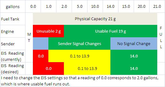
Here is the revelation! When I calculated the programming values the first time I set the full reading at 19 (usable fuel) and this time I set it at 14, which is the fuel level where the display stops changing. The GRT instructions talk about this in Step 6 of the instructions but I did not realize the implications of not knowing where the display stops changing.

When I redid the calculations the set points changed as follows:

AuxSF originally 345 now 255
AuxOFF originally 973 now 719

When I entered the set points into the EIS and checked the tank level readings with one full and one empty tank the full tank read just a little high so I changed the AuxSF to 256 and it then read 14.0 gallons - the place where the reading started changing as I drained the tank. The empty tank read 0.0. I added about 1 gallon to the empty tank and the reading was still 0.0. I added about 1/2 gallon more and it showed 0.5 gallons.

So now as I fly a reading of 14 means >= 14 gallons remaining, anything between 13.9 and 0.1 should be accurate, and when it hits 0 I know that I have no more than 1 gallon left.

I have some long trips coming up so I will test my work by flying long enough legs to get down in the indicating range and then checking it against the fuel totalizer.

BTW I know that these readings are quite a bit different than other people came up with. I have a note that 358/1117 is close to what a lot of people have calculated, but I don't know who said it. It's in the forums here somewhere. That's why I am not yet claiming victory against the dreaded AuxOFF/AuxSF. I could be very wrong but I feel pretty good about the fuel flow and totalizer function. That seems pretty darn close so the fuel levels are just backups.

Here is a graphic that may help us understand things. When I did this I realized that when the EIS tells me I have 1 gallon left I am just about to run out of usable fuel. I need to recalculate things so that when the EIS says 0.0 I am out of usabe fuel.

564357316_B3pbk-M.jpg
 
Last edited:
You'll probably want to check how much fuel you consume and how much the totalizer thinks you consume. I believe GRT wants you to run about 100 gallons before continuing to tweak the EIS config values but you should easily get it to be accurate within .5 gallons over 40 gal. After running through a full tank of gas mine shows I've used about a half gallon more than actual.
 
Back
Top