Bob,
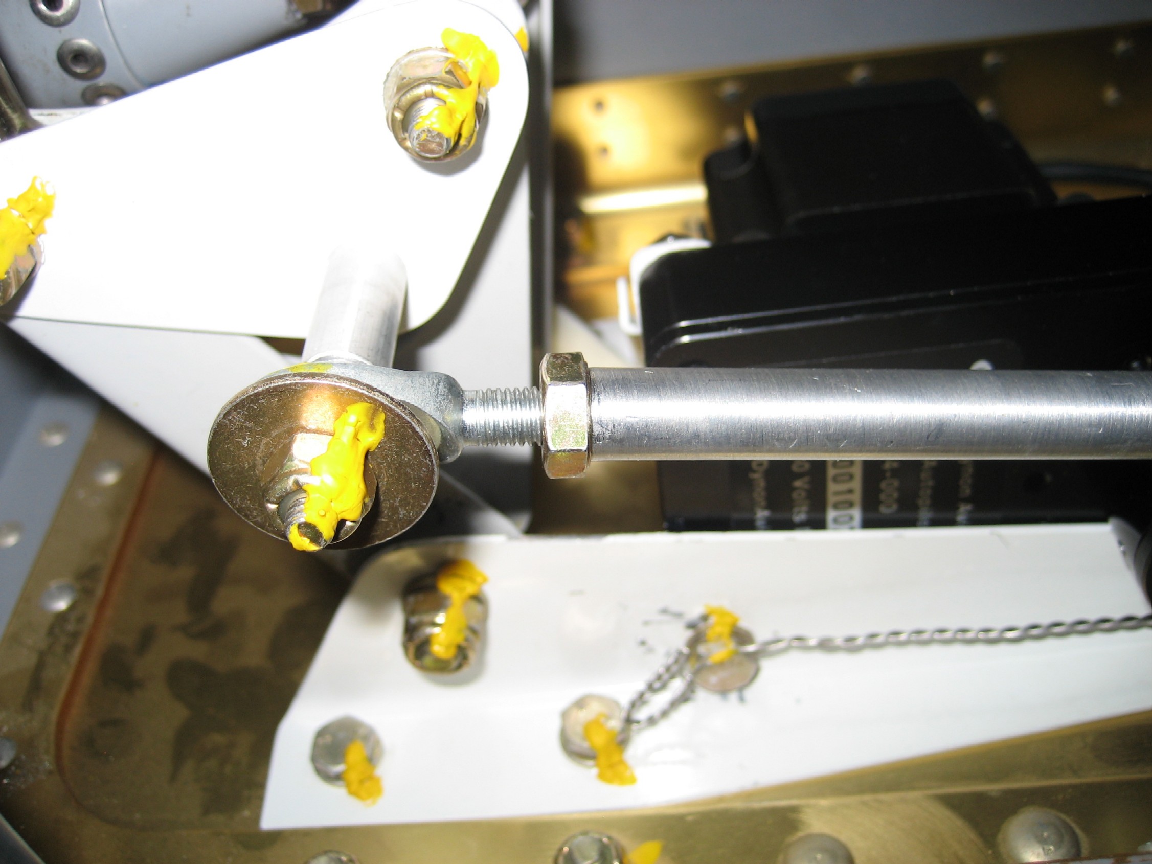
I used a silver sharpie to mark a line across the "shear screw thick washer" and the servo arm. The arm would move about 2 deg. each way with the servo locked using the test setup. End of arm movement about 3/16"? I should of noted better. The castle nut was finger tight, so when I reinstalled I tightened just snug to the next cotter hole. The shear screw is a 6-32 brass capscrew 3/8' long. When it was loose it would rock back and forth, allowing movement.
When I do my pitch servo (lots of ele. movement) I will measure the arm hole vs shear screw. It did feel tight but not a friction fit. Just checking
")
Trying to be clear-- there is some small servo gear lash. And after I re-assembled, the shaft to arm movement went away
Hope this helps.
PS If anyone works on this you have to make sure the shear screw
will break as designed. Not all glued up etc.