What's new
Van's Air Force

Don't miss anything! Register now for full access to the definitive RV support community.

Air Cooled VS. Water Cooled

Rotary10-RV

Well Known Member
Ok Folks,
Lets be realistic here. First the basic equation Q=h A (delta)T. In the engineering world many factors have already been worked out. Q is the rate of transfer of heat. BTU's/Hr. h is the coefficient of heat transfer. interestingly the transfer from a cast iron surface (turbulent) is 1.0. Aluminum is a but better but for now lets say 1.0. Ok now our equation looks much simpler Q = (1.0) A (delta)T. So let's assume the area is one square foot. The result is greatly simplified. Q= (1.0) (1.0) deltaT. So the rate of transfer is pretty simple. The RATE of exchange is about 2.25 greater for a air cooled engine compared to a water cooled engine. There are many other considerations for a engine but let's keep this as simple as possible. That solution seems pretty obvious, BUT that equation was simplified to the same exact AREA.
Area is the other major adjustable term. h of Water to iron, or better aluminum is 60-80 times greater than to air, so the second needed transfer can practically be discounted in this discussion since the air to radiator rate is going to determine the rate of transfer.
Based on the transfer rate alone, I would say that AC (air cooled) engine has a tremendous advantage. What everyone is ignoring in the equation is A or area. On a air cooled engine the maximum AREA is practically fixed. The heat exchanger (radiator) for a WC (water cooled) engine can be selected based on the heat rejection required. The modern radiator also packages a great deal of area into a given volume. One of the problems manufacturers had with producing cylinders and heads that would hold up on the large AC engines was making enough fin area to dissipate heat at high power and boost. I've got several old War Report findings from Pratt and others that mention the need to carefully machine the fins on the large cylinders to get fine enough pitch for heat rejection. On later versions you will even see a corrigated inserts between fins to increase area and help lessen ringing noise.

What this information shows someone that looks at it rationally is there are advantages and disadvantages to BOTH.

Air Cooled
Advantages: Simpler, high rate of heat rejection, light for a given size.

Disadvantages: Fixed max dissipation, lower specific output for a given size, limited layouts for a high output, IE radial or opposed. high normal operating temperature requires better oils and fuels.

Water Cooled
Advantages: Highest specific output for a given size, freedom of configuration, IE V upright or inverted, radial, opposed, unconventional rotary or barrel engines. heat exchangers can be located remotely and sized for output. Lower normal operating temperature lessens oil and fuel requirements.

Disadvantages: more complex, weight of secondary coolant, weight of remote mounted heat exchangers. Coolant pump is a wear consideration. System must be designed to prevent trapped air. plumbing is more complex and must be protected.

Conclusion: I could make an arguement for either system. The winner in a given situation would depend on the desired characteristics of the engine package. I know this ignores ducting, plenums, and a host of other factors but an arguement can still be made for both types. While I personally like water cooled engines I didn't even put a heater on the list. I will now don my fire suit. Fire away.
Bill Jepson
 
When I first considered building in 1988 I was all gung-ho about doing a conversion. A fellow pilot asked me if I had ever driven or ridden in a car that experienced a coolant leak/hose/pump issue that created steam. Well.... yes, in fact, more than once. Then he asked what happened next? We pulled over to the side of the road. :(
 
Really well done analysis, but there is one more consideration when it comes to aircraft:

The heat exchanger (radiator) for a WC (water cooled) engine can be selected based on the heat rejection required. The modern radiator also packages a great deal of area into a given volume.

The more area exposed, and the higher volume of air required, the more cooling drag is created. This were in the aircraft application the high delta t makes a huge difference in the ability to design for low drag. This seems especially true in tractor configurations.

This could be designed around, no question about it. Ross is probably doing the most with that right now with his 10 package that has a dedicated P-51 style belly scoop and ducting. But, to overcome the issue proper inlet and outlet ducting will be required.

A dedicated airframe design might be the best way to go. At the other end of the spectrum is bolting two or three fat rads to the front of the engine. Most of these (EGG) have gotten better and better inlets to the rad, but the outlet is just the bare back of the rad...not optimum at all, but probably the easiest way to retrofit to a design originally intended for aircooled.
 
Q=M Cp deltaT

Where Q is the desired heat rejection, Cp is the specific heat capacity of air (same in either case). M is mass flowrate of air thru radiator or fins.

Assuming your engine is roughly the same efficiency true if naturally aspirated.

Then in order to get the same heat rejection the water cooled engine needs 2* more mass flow of air thru the rad.

More cooling air means more drag.

Now of course the advantage of a water cooled engine is you can put rads anywhere...But in terms of minimising drag they are starting a bit behind the pace.

Until we have true side by side flyoffs with fully instrumented engines it will be hard to come to real conclusions of how much of a detriment this issue is in terms of speed attained for unit of fuel consumed.

Frank
 
In my experience most coolant leaks beyond potential issues immediately after servicing or modifying a cooling system, (on the ground) is usually related to neglect or just too long a service period for the components and environment involved.

I can certainly see concern about not being able to pull over to the side of the road. One way around this would be to use non-aqueous coolants available. In fact I think I've seen this advertised within the aviation crowd I've been purusing for a short time compared to many of you. I have four gallons in my garage waiting for what I originally thought we be a ground based application. I have seen it run in a land speed application that was cooking pretty good at the end of a five mile run under power. It took care of that problem. Coolant temps got high, intake air temps got high, compression ratio was about 12.5:1. Density altitude was probably pretty high in the 7-8K range, airflow to the radiator or the radiator itself was insufficient for an extended period in the conditions we were running. That car has about a four gallon fuel tank.

In an aircraft application whether taking part in some of the benefits of non-aqueous coolant and the lack of potential steam present, or following a more traditional water based coolant mix, the hardware in the system need to be top notch and checked/replaced often, like every two or three years. Expenses in aviation tend to run high. Surely opting for highest quality material available within reason, and limiting their service life for safety, isn't going to make a big dent in the whole scheme of things.

I will add, non-aqueous coolants are generally less efficient at removing heat that traditional systems, but there is the added benefit of pressureless or very low pressure systems and no steam, theoretically just fluid loss, hot fluid at that, and an unexplained coolant temp increase that may require a precautionary landing, depending on the nature of the leak.
 
Really well done analysis, but there is one more consideration when it comes to aircraft:

The heat exchanger (radiator) for a WC (water cooled) engine can be selected based on the heat rejection required. The modern radiator also packages a great deal of area into a given volume.

The more area exposed, and the higher volume of air required, the more cooling drag is created. This were in the aircraft application the high delta t makes a huge difference in the ability to design for low drag. This seems especially true in tractor configurations.

This could be designed around, no question about it. Ross is probably doing the most with that right now with his 10 package that has a dedicated P-51 style belly scoop and ducting. But, to overcome the issue proper inlet and outlet ducting will be required.

A dedicated airframe design might be the best way to go. At the other end of the spectrum is bolting two or three fat rads to the front of the engine. Most of these (EGG) have gotten better and better inlets to the rad, but the outlet is just the bare back of the rad...not optimum at all, but probably the easiest way to retrofit to a design originally intended for aircooled.

I believe the best solution for either an Air or Water cooled engine is for the airframe to be designed around it. If you look at a P51 that huge fighter is about the same width at the firewall as a RV-10. Much deeper vertically, but that indicates the flexibility possible with water cooling. Then again no one can argue that an F8-F Bearcat tears through the air with it's large round fuselage. I'll see if I can post a couple of the NACA war reports on the ducting. It shows that the wide open radiator rear isn't that bad, IF and it an important if, the area behind the radiator is unobstucted for at least 4x the core thickness. This isn't met with an Egg or any front mounted radiator that I have seen. That is in fact my biggest gripe about the Egg and several other conversions. That said, just because the radiator looks solid doesn't mean that the airflow is worse than in a Lyc plenum. You need to measure both with a manometer it you want to know rather than guess.
Bill Jepson
 
Where Q is the desired heat rejection, Cp is the specific heat capacity of air (same in either case). M is mass flowrate of air thru radiator or fins.

Assuming your engine is roughly the same efficiency true if naturally aspirated.

Then in order to get the same heat rejection the water cooled engine needs 2* more mass flow of air thru the rad.

More cooling air means more drag.

Now of course the advantage of a water cooled engine is you can put rads anywhere...But in terms of minimising drag they are starting a bit behind the pace.

Until we have true side by side flyoffs with fully instrumented engines it will be hard to come to real conclusions of how much of a detriment this issue is in terms of speed attained for unit of fuel consumed.

Frank

I disagree only slightly, Your assumption is that ALL the air is in contact and not in a free stream past the cooling fins. My contention is that for a given volume of air the radiator will in fact contact more of it and be much better at approaching theroetical. I was trying to keep it as simple as possible.
Bill Jepson

Correct Bill. With a diverging/ converging duct, we can also slow the air down through the rad core which results in more contact time with the fins, lower pressure drop across the tubes/ fins and can re-accelerate the air closer to free stream velocity. Despite the lower Delta T, we can use each pound of cooling air quite effectively. Is it better than air cooling? We don't know without some real world testing.

Modern rads are all aluminum and have thin tubes and pierced, louvered fins- ideal for high rates of heat transfer. The K value for aluminum is about 3 times that of steel. Steel therefore makes a poor choice for a heat exchanger say a Lycoming barrel compared to a Rotax or Porsche barrel. Copper is quite a bit better than aluminum even but is very heavy and the thickness of the tubes and effective ways to joining tubes to fins are harder without creating thermal barriers.

As far as the non-aqueous coolants like Evans NPG+ go, I've tested it back to back against 30% ethylene glycol/ 70% distilled water and a dose of Redline Water Wetter to reduce surface tension. Under the same ambient air temps and same IAS, coolant temps dropped an average of 9C in the climb using the water based mix. Evans offers a very high boiling point (375F) as does pure ethylene glycol but a much lower rate of heat transfer than water based mixtures. 9C is very significant in the climb on a liquid cooled engine. We are able to climb at 90 knots IAS at an OAT of 25C at full climb power (4600 rpm and 35 inches) without the coolant temps exceeding 92C.

With regards to rads, I've just finished flow benching 4 different common heat exchanger types for pressure drop. The often used large GM evaporator cores are the worst at 5.75 inches H2O compared to a Visteon type core with oval tubes at only 2.75 inches. Pressure drop through the coolant passages will have to measured next and then temperature drop on a test rig. This will then give us a better picture on what type and shape of HE (heat exchanger) gives the best performance per unit area and unit pressure drop.

Good thread Bill, maybe some useful info can be exchanged here.:)
 
Last edited:
Points to consider

When I first considered building in 1988 I was all gung-ho about doing a conversion. A fellow pilot asked me if I had ever driven or ridden in a car that experienced a coolant leak/hose/pump issue that created steam. Well.... yes, in fact, more than once. Then he asked what happened next? We pulled over to the side of the road. :(

This is a very valid point. I take this time to mention that MOST forced landings of experimentals are caused by NON-ENGINE systems. Fuel feed failures are greater than 50% of forced landings from the FAA stats. This is for certified and auto conversions. All this means is that we must pay attention to sub systems, JUST LIKE THE BIG THINGS. A fuel feed failure can kill you just as dead as a thrown rod if it makes your engine stop at a bad moment. We can roll through all the possibilities in a best practices thread. I am a subscriber to several Rotary engine lists. One of the guys started a Wiki page with best practices that can be updated by the guys from the forum, an excellent idea IMO.
Bill Jepson
 
I do a lot of historical reading of technical reports on WW2 engine development as much can be learned.

The coolant pressures used on the P51 are up to 50 psi! to raise the boiling point and Delta T. Max temps on the Merlin were 130C. The P51 used 60/40 EGW. Early Spitfires used lower pressures but pure EG. Later marks of the Hurricane used 30/70 EGW mixtures as more powerful Merlins were introduced to avoid have to redesign the radiators.

Some other tidbits include speeds with open and closed rad flaps. Typically closing the flaps at full power was worth between 10 and 24mph more speed depending on the airframe. Drag is reduced by reducing massflow through the HE (lower pressure drop).
 
Mass-O-Kiss-Tick????

This thread is shaping up to generate a headache almost as bad as the torsional vibration thread:eek:

Why, oh why do I keep reading this stuff??:confused:
 
This thread is shaping up to generate a headache almost as bad as the torsional vibration thread:eek:

Why, oh why do I keep reading this stuff??:confused:

Mike, we are all going to behave ourselves.:rolleyes::D

The TV thread was great and has generated some interest on some other forums. I hope this one will give people some good ideas too. Please anyone with actual bench or flight test data/ experiences- contribute.
 
Conclusion: I could make an arguement for either system.
Fly a Rotax and get both. ;)

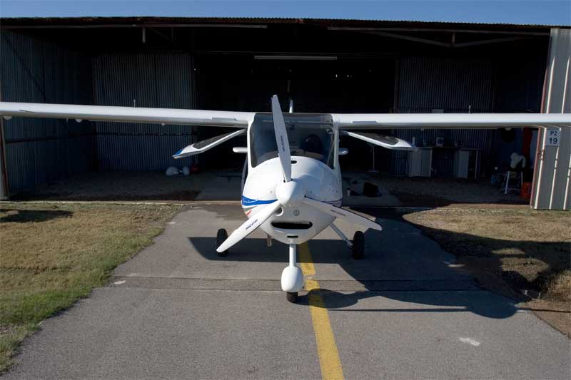
Here's a shot of a 912S install from head-on. The small round inlet on the right of the airplane's centerline (left on the photo) is the air cooling scoop, about the size of a fist. Oil cooler and radiator are below. Note 2" HVAC foil tape across the top of the oil cooler to reduce cooling for winter temps:
front_ADS.jpg


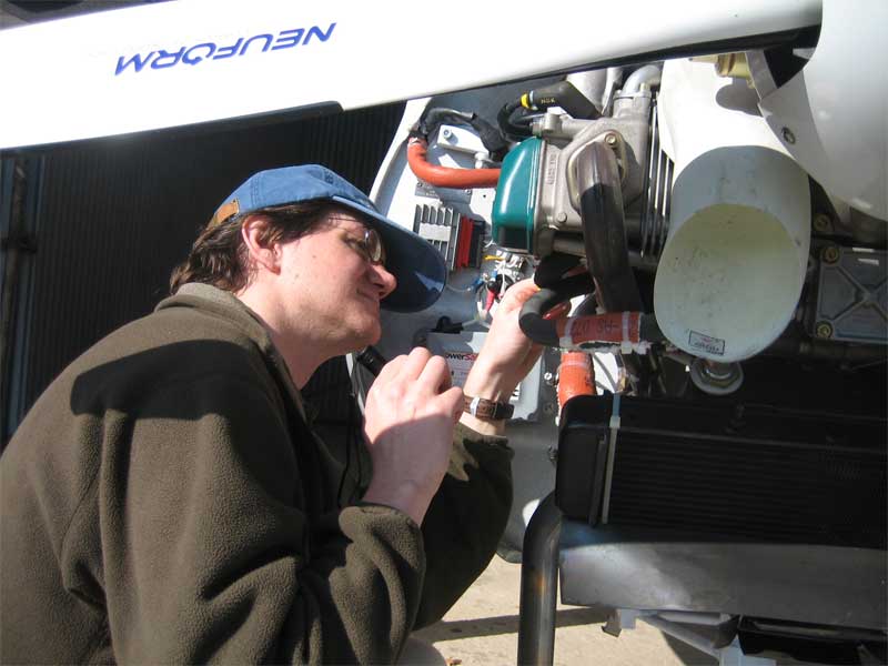
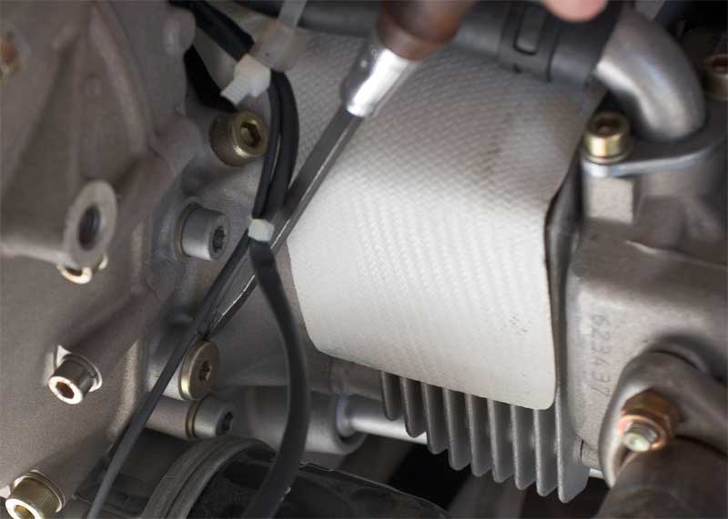
Here is a detail of the air baffling. The baffle appears to be made from fiberglass and directs air down through the fins on the cylinders; you can also see the coolant jackets on the heads. The air cooling is sufficient to allow the 912 to operate at part power settings without serious overheating should you loose the coolant system in flight. (tool is point to the magnetic plug, which you need to check religiously to make sure your gearbox isn't wearing excessively).

air_cooling_web.jpg


baffle_web.jpg


To be honest, the coolant system is one more thing to check on pre-flight and in order to do it right, you have to remove the cowling. It's only a 60 second job in the CT, but a better cowling door would make it easier.

TODR
 
Last edited:
Mike, we are all going to behave ourselves.:rolleyes::D

The TV thread was great and has generated some interest on some other forums. I hope this one will give people some good ideas too. Please anyone with actual bench or flight test data/ experiences- contribute.

Hopefully soon! I think Dan and Jan were doing a lot of experimenting with cooling on Dan's -10.
 
I believe the best solution for either an Air or Water cooled engine is for the airframe to be designed around it. If you look at a P51 that huge fighter is about the same width at the firewall as a RV-10. Much deeper vertically, but that indicates the flexibility possible with water cooling. Then again no one can argue that an F8-F Bearcat tears through the air with it's large round fuselage. I'll see if I can post a couple of the NACA war reports on the ducting. It shows that the wide open radiator rear isn't that bad, IF and it an important if, the area behind the radiator is unobstucted for at least 4x the core thickness.
Bill Jepson

Don't forget the Jumo powered FW190D/TA-152. They used an annular radiator arrangement and were plenty fast. That type of arrangement may work well in a -10 provided the LS engines are thin enough, as they appear to be in photos.

It doesn't hurt that at a distance people will think you have a radial.:D
 
With a diverging/ converging duct, we can also slow the air down through the rad core which results in more contact time with the fins, lower pressure drop across the tubes/ fins and can re-accelerate the air closer to free stream velocity. Despite the lower Delta T, we can use each pound of cooling air quite effectively. Is it better than air cooling? We don't know without some real world testing.
This is one of the things that keeps rattling around in my head. Another consideration that I don't think I've ever seen mentioned is the fact that a good diverging/converging duct could (should) be made with smooth internal surfaces, free of drag creating items such as pushrod tubes, spark plug wires, intake/exhaust pipes, etc. Sure, straight aircooling may be more efficient without the liquid medium from a thermal standpoint, but the whole system needs to be taken into consideration.
 
Mike, we are all going to behave ourselves.:rolleyes::D

The TV thread was great and has generated some interest on some other forums. I hope this one will give people some good ideas too. Please anyone with actual bench or flight test data/ experiences- contribute.

Ross buddy, I am not concerned about folks getting rude/off track-------it is all this technical stuff, and higher math, that is so far above the comprehension of we mere mortal men.

Ach------where is my Advil???
 
Good points

Most of these (EGG) have gotten better and better inlets to the rad, but the outlet is just the bare back of the rad...not optimum at all, but probably the easiest way to retrofit to a design originally intended for aircooled.
That is a good point John. I would say look at the new (EGG) cowl with square inlets. The radiator outlets do just dump out into the cowl, but he has improved from imprevious designs. They look (don't know dimensions) larger than a Vans and certainly James cowl inlet area. I'll say by inspection the drag is higher. Why not get less cooling drag? Well easier said than done. A lot of work has been thrown into optimization of air cooling aircraft engines down to the fin spacing, height and thickness. The cowl designers have been optimized through more research.

The coolant pressures used on the P51 are up to 50 psi! to raise the boiling point and Delta T................Some other tidbits include speeds with open and closed rad flaps. Typically closing the flaps at full power was worth between 10 and 24mph more speed depending on the airframe. Drag is reduced by reducing massflow through the HE (lower pressure drop).
Great post. The pressures where much greater in many aircraft coolant systems. I remember in the 80's the early V6 and V8 auto conversions (no particular) had problems with hot spots, steam pockets and cavitation. So how to get a REAL HIGH PRESSURE pump radiator system? The stock pump will not due, will it?

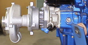
The "cool jug" guys (water cooled cylinder/heads for Lycs) ran a separate mechanical pump off the accessory case at very high pressures. I talked to them once and the pressures I think where 15-20 psi (typical) but the flow is very high. They don't say much on their site but this might be worth a quick read:

http://www.liquidcooledairpower.com/cj-pump.shtml

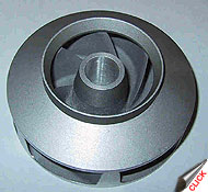
pic_pump1_lg.jpg
pic_axialimpeller_sm.jpg


It will be great to read about you twin turbo Subaru RV-10 with a P-51 belly scoop set-up, when you get flying Ross. You have to go with a streamlined P-51 cowl to match the belly radiator. Long coolant lines are begging for higher pressures. If the radiator size, thickness and fins/tube spacing if carefully selected should cool very nicely. Will the stock water pump be up to it? Will you have redundant or supplemental electric water pump?

Coolant (what not to use)
In a related topic the General Motors Dex-cool lawsuit has been settled. The class action covers 35 million GM vehicles manufactured from 1995 to 2004. GM's "Dex-Cool" coolant allegedly caused serious car problems such as: corroded clogged radiators, eroded water pumps, rotten radiator hoses, leaky cooling system gaskets, chronic overheating and engine damage from coolant sludge, as well as head gasket and intake gasket failure possibly resulting in engine damage. GM marketed Dex-Cool coolant as good for 150,000 miles or 5 years without needing to be flushed and replaced with new coolant. GM agrees to pay up to $800 per car for repairs.
 
Last edited:
The main difference is how heat is removed from the hot parts of the engine. An air cooled engine use only conduction through metal, and this is not particulary effective regarding heat transfer rate. A liquid cooled engine transports the heat with the liiquid, and this is orders of magnitude more effective

A liquid cooled engine is simply an air cooled engine where channels for liquid flow are drilled into the fins and the core, and liquid is flowing in a loop from the core to the fins and back. For the same temperature in the core, which engine requires more coolinng air? There is noo difference, only the radiator can be made much morre effective, so the liquid cooled engine will be the better choice.
 
Ive been studying various water cooling systems over the last few years while building my RV, mostly in reference to the Mazda rotary engine. There seems to be two groups of thought, and both have made examples that seem to work effectively.

The Egg folks and Tracy Crook prefer the small densely packed (4-5" thick) radiators placed in front of the engine, which restrict the airflows out the back. These generally cool quite well at high speeds due to the high pressure of 200 mph air, but tend to be inefficient at slower (climb, during taxi) when the pressure is lower, and they present close-to-the-same drag profile as the air-cooled heads do.

The other school (where I'm personally leaning, btw) places a much larger, full-size aluminum automotive radiator that is less densely packed and thinner (maybe 1.5-2" thick) placed either parallel to the engine, or beneath it, or both. This arrangement is obviously more complicated and requires well designed wedge diffusers with ducting before and after the radiator. Because the radiator is thin, there is far less restriction/drag involved, and the outgoing air can be controlled with a flap; which, when closed, can substantially reduce the cooling drag when it is not needed in cruise. Because high pressures are not required for efficiency, this design cools well at high and low air speeds. The thing I like about this particular water cooling design, is that once it is proven effective in the particular application, it will work without problems from then on, with no worry about limiting power, shock cooling, or hard warm restarting.

The rotary engine is so much smaller than Lycs or Subis, either radiator orientation works quite well.
 
Last edited:
Slightly off track

Great post. The pressures where much greater in many aircraft coolant systems. I remember in the 80's the early V6 and V8 auto conversions (no particular) had problems with hot spots, steam pockets and cavitation. So how to get a REAL HIGH PRESSURE pump radiator system? The stock pump will not due, will it?

The "cool jug" guys (water cooled cylinder/heads for Lycs) ran a separate mechanical pump off the accessory case at very high pressures. I talked to them once and the pressures I think where 15-20 psi (typical) but the flow is very high. They don't say much on their site but this might be worth a quick read:
It will be great to read about you twin turbo Subaru RV-10 with a P-51 belly scoop set-up, when you get flying Ross. You have to go with a streamlined P-51 cowl to match the belly radiator. Long coolant lines are begging for higher pressures. If the radiator size, thickness and fins/tube spacing if carefully selected should cool very nicely. Will the stock water pump be up to it? Will you have redundant or supplemental electric water pump?

George,
I did some snipping here but I think you missed what Ross was talking about the 50 PSI comment. He was talking about pressurizing the SYSTEM to 50 PSI then the boiling point is sagnifigantly raised. They were also running a high level of EG mix which raises the boiling point even more. The 50 PSI system wouldn't change the power required to flow the mix through the system, which IS a factor. A good 50-60 GPH pump will consume 5 HP at design RPM. I'm sure the designers of the engine were trying to raise the normal operating temperature so there would be less of the delta T difference we were talking about at the beginning. So it isn't the stock water pump that is inadaquate, rather it is the radiator and radiator pressure cap. Cooling can be improved, usually by increasing the water flow, but there are limits and the pumps needed consume ever more HP.
Bill Jepson
 
This thread is shaping up to generate a headache almost as bad as the torsional vibration thread:eek:

Why, oh why do I keep reading this stuff??:confused:

Sorry Mike! If it's any consolation the TV thread hurts my head too. I need to look up too much stuff and it makes my hair hurt:D
Bill Jepson
 
Don't forget the Jumo powered FW190D/TA-152. They used an annular radiator arrangement and were plenty fast. That type of arrangement may work well in a -10 provided the LS engines are thin enough, as they appear to be in photos.

It doesn't hurt that at a distance people will think you have a radial.:D

I've always admired these aircraft and have a big painting of a D10 in my hangar. You just need to find someone who will build you a round rad.:)
 
Last edited:
The OE water pumps on any modern engine that I've played with are more than adequate for very high sustained power levels. The Sube ones are driven off the cam belt on the EJ/EG series so if that breaks, you have other things to worry about- like a suitable field! Modern water pumps are super reliable and with aircraft maintenance procedures, I would never expect a failure on ones of these. I have not seen a failures in about 20 years and they give plenty of warning with seals or bearings. I've seen totally roasted pumps go many more months before getting replaced. They might seep a bit and grumble but they are tough.

Higher pressure just needs a higher cap pressure as Bill stated

The oblique rad setups probably show high drag compared to traditional layouts. No WW2 aircraft used these setups and these guys were pretty smart. Turning airflow 180 degrees is usually a recipe for high pressure loss.

My RV10 will retain the stock cowling for intercooler and oil cooler placement and airflow. Without the turbos, I could go with a more streamlined cowling- but I hate glass work anyway.

I use good old Prestone glycol- same as the P38.:)
 
img1926qo8.jpg

This is my set-up with two large radiators which I think will be highly effective on the ground and will probably create significant drag at 200mph. Once I get everything running I will start working on some type of cowl flap system. Baby steps. Since it is pretty hot/warm down here 2/3's of the year I need to insure that my engine stays cool on the hots days.
 
Last edited:
Bring $$$$ LOTS!

I've always admired these aircraft and have a big painting of a D10 in my hangar. You just need to find someone who will build you an round rad.:)

Ross I'm sure you are tongue-in-cheek about the round rad. I should mention that the tapered curved radiator available for the Yamaha 750cc road racer was a great piece of aluminum sculpture, for a mere $10,000.00! I'd really hate to crash one of those!
Bill Jepson
 
I didn't say it would be cheap.:D

Just listing it as another example of an aerodynamic and efficient radiator install. Minimal if any turns, close to the engine, nice exit distance to work with, and a good low pressure point to exit.

Would need custom radiators for sure, but may not be that expensive if on each side use half circles (I use that description loosely), or tapered ones with creative inlet ducting.


Ross I'm sure you are tongue-in-cheek about the round rad. I should mention that the tapered curved radiator available for the Yamaha 750cc road racer was a great piece of aluminum sculpture, for a mere $10,000.00! I'd really hate to crash one of those!
Bill Jepson
 
Ross I'm sure you are tongue-in-cheek about the round rad. I should mention that the tapered curved radiator available for the Yamaha 750cc road racer was a great piece of aluminum sculpture, for a mere $10,000.00! I'd really hate to crash one of those!
Bill Jepson

I was looking at a curved rad for a 250 GP bike a couple weeks ago. Very cool. I did not ask what it would cost.

The ground cooling thing is a bit of a bear with some installations. I've measured the pressure at various parts of the prop disc and it is pretty minimal near the prop shank. For decent ground cooling it seems that inlets outboard of 1/3 prop span give the best chance of success.

Getting good ground cooling, good climb cooling and no excessive drag in cruise where massflow is high and power is somewhat lower really demands some sort of cowl flap especially if you are not using a thermostat. The WW2 stuff generally did not use 'stats to restrict water flow. In flight, we are at odds with the shape of the radiator as well for what works well on the ground with low Delta P and high area probably hurts for drag in cruise. Flow bench tests show that pressure drop is not proportional to depth which is good but a thick rad is essentially useless on the ground as no air penetrates the core at the low Delta Ps available from the prop at idle. It is all a big compromise.

I did some other tests on the rad exit duct with 3 big centrifugal blowers and wool tufts. My thought was that turbulence could be reduced in this area using a double hinged flap to fill in the area aft of the flap at partially closed settings. The tufts showed this was not the case at all. The straight flap had less turbulence than the complicated solution I dreamed up. Easier to build too.
 
DIFFERENT SHAPES?

Ross and Wade,
Didn't the round radiator system have a forced air fan? Kind of a slotted ducted fan? perhaps that was the FW190 oil cooler. I'm not right up on those radiators. The ability to change shape of the heat exchanger is one of the advantages listed in the WC plus column. An air cooled radial does fit this area better though, and that is without a very expensive radiator.
Keeping to the topic the ability to remote locate the radiators in an area that would normally be wasted space is a water cooled plus. The P-51 is an excellent example. The ME-109 had a good in-wing radiator as well. The 109 also had a interesting ability to split the inboard flap for good ground cooling.
Bill Jepson

I have thought about this many times. They make this tubing for installing under tile floors to keep them warm. It would be great if you could bond these to the wing skins. You could cool the engine and heat the wings (great against icing). Downside is a very complex piping network and added weight.
 
Ross and Wade,
Didn't the round radiator system have a forced air fan? Kind of a slotted ducted fan? perhaps that was the FW190 oil cooler. I'm not right up on those radiators. The ability to change shape of the heat exchanger is one of the advantages listed in the WC plus column. An air cooled radial does fit this area better though, and that is without a very expensive radiator.
Keeping to the topic the ability to remote locate the radiators in an area that would normally be wasted space is a water cooled plus. The P-51 is an excellent example. The ME-109 had a good in-wing radiator as well. The 109 also had a interesting ability to split the inboard flap for good ground cooling.
Bill Jepson

The BMW 801 radial powered FW-190 used a ducted spinner and fan on the prototype. The D series used an inverted V12 Jumo liquid cooled engine with annular radiator and was about 20mph faster with about the same hp over the radial engined A-8. The TA-152A used the Jumo as well and could reach 443mph. The TA-152C used a DB-603 inverted V12 liquid cooled again, with annular rad, nitrous and water methanol injection- top speed 463mph. The planned S model was to have a 3000hp Jumo 222A-3!

The HE-100 set a world speed record of 463.92 mph (low altitude) in 1939 using a special 1800hp DB601 and surface conduction cooling- no rad. Production versions used a retractable rad and could do 416 mph on only a 1020hp DB-601. Very impressive.

The ME-209-2 used a 1770 hp Jumo 213 with annular rad as was capable of 458mph.
 
Seems like a good idea, but sadly isn't

I have thought about this many times. They make this tubing for installing under tile floors to keep them warm. It would be great if you could bond these to the wing skins. You could cool the engine and heat the wings (great against icing). Downside is a very complex piping network and added weight.

Todd,
There are several factors why this unfortunately won't work. Peter Garrison in the "Technicalities" column did a nice article on this very subject. There are 2 major factors. First, there is simply not enough area as a "flat plate" heat exchanger. (discounting all the problems with fastening the tubing etc...) Second, we are trying harder and harder for lamilar airflow on most of our wings. This causes a boundry layer on the wing surface that for heat exchange purposes forms an insulating layer between the lamilar flow and the surrounding air. This effect is large, the heat transfer coefficient is almost
10X worse. Actual examples have been tried with very poor results. Sadly it doesn't even help enough to be an effective means of de-icing. Running the engine exhaust is another de-icing idea that didn't proove worth the effort.
Check out the Flying back issues, search Peter Garrison and you should fine the article easily, it is worth the effort. Peter does his research and writes entertainingly.
Bill Jepson
 
Ross is right the radial had a fan for ground ops. Best as can remember the Jumo did not but I will check my book tonight.

Wing radiators are another good idea for investigation. I forget what plane they were installed on right this minute but it is mentiontioned in "Kuchemann & Weber , Aerodynamics of Propulsion" (good read) , that had radiators in the wing with inlets centered in the leading edge of the wing root. Lots of room for nice diffusers and it takes advantage of the high pressure area in front of the wing edge and is exhausted on top near the trailing edge. Of course I don't know how that would work given the -10 wing structure, but it would be low drag.

Thanks alot for you guys pioneering work. Learning alot and you should have it all figured out by the time I am ready to build my -10. After I finally finish my -8 of course.:)
 
Last edited:
wing rads

Would it not work to build small radiators into RV7/8 wings between the spars much like a spitfire or BF109 rad? Possibly with a movable flap on the aft side. It would be embedded into the wing with only a portion exposed below the lower wing surface to allow for air to slow prior to contact with the rad surface.

Bevan
RV7A wiring
 
Todd,
There are several factors why this unfortunately won't work. Peter Garrison in the "Technicalities" column did a nice article on this very subject. There are 2 major factors. First, there is simply not enough area as a "flat plate" heat exchanger. (discounting all the problems with fastening the tubing etc...) Second, we are trying harder and harder for lamilar airflow on most of our wings. This causes a boundry layer on the wing surface that for heat exchange purposes forms an insulating layer between the lamilar flow and the surrounding air. This effect is large, the heat transfer coefficient is almost
10X worse. Actual examples have been tried with very poor results. Sadly it doesn't even help enough to be an effective means of de-icing. Running the engine exhaust is another de-icing idea that didn't proove worth the effort.
Check out the Flying back issues, search Peter Garrison and you should fine the article easily, it is worth the effort. Peter does his research and writes entertainingly.
Bill Jepson

This can't be right. Either it would be a poor cooler (for the liquid) and be a good heater (as in de-icing), or be a good cooler and poor de-icer. For de-icing the only requirement is to rise the temp on the surface above 0 deg C and keep it there. This is used in pavements etcetera, and works perfectly. I guess this would be more anti-ice than actual de-ice because it won't crack the ice.

Besides, laminar flow is in no way an insulator with regard to heat transfer, the air is still mooving. It is simply not as good as turbulent flow. If I am not mistaken, this principle of cooling has been used successfully on German pre-war fighters, or racers.
 
Surface conduction cooling has been done successfully in the 1920s and 1930s on race aircraft such as the previously mentioned HE-100 and the Macchi M.C.72 float plane- both world speed record holders. They both required huge amounts of exposed area and in the latter case, the rads were copper tubes- extremely heavy alone but add to that the huge coolant volume required. Payload, ease of construction and maintenance are not factors on race aircraft.

So it can work but it is not practical on an RV airframe from either a weight or complexity point of view. Getting a good, reliable thermal bond to the wing skin would be a nightmare IMO. Routing of coolant lines around the RV fuel tanks is very problematical.

The Leading edge rads used on the early Tempest, Hornet and Whirlwind appeared to be an excellent low drag solution but don't fit into an RV because of the fuel tanks again. Wing rads of any type on RVs are just plain hard to do because of the structure. Wing rads often suffer poor pressure recovery and separation due to their relatively short lengths and abrupt turns. This has been noted on the ME109 and Spitfire setups.

On RVs we are pretty much left with cowling or fuselage mounted rads practically speaking. We know from pressure testing that cheek mounted rads are not very efficient but they do simplify plumbing considerably- hence their popularity.

My feeling is that a good compromise would be a rad mounted under the engine in a dedicated diverging/ converging duct with exit flap being fed by a Cheyenne type inlet maybe 6- 8 inches below the spinner and a few inches aft of it. This might look like the Wankel powered RV8s from a few years back externally but with a more efficient radiator sealed to the duct.

Alternately, you can do what I'm trying on the RV10 but this presents many other difficulties.

It will be interesting to see how Todd's and Bill's layouts work.
 
Not impossible, but not practical

Surface conduction cooling has been done successfully in the 1920s and 1930s on race aircraft such as the previously mentioned HE-100 and the Macchi M.C.72 float plane- both world speed record holders. They both required huge amounts of exposed area and in the latter case, the rads were copper tubes- extremely heavy alone but add to that the huge coolant volume required. Payload, ease of construction and maintenance are not factors on race aircraft.

So it can work but it is not practical on an RV airframe from either a weight or complexity point of view. Getting a good, reliable thermal bond to the wing skin would be a nightmare IMO. Routing of coolant lines around the RV fuel tanks is very problematical.

The Leading edge rads used on the early Tempest, Hornet and Whirlwind appeared to be an excellent low drag solution but don't fit into an RV because of the fuel tanks again. Wing rads of any type on RVs are just plain hard to do because of the structure. Wing rads often suffer poor pressure recovery and separation due to their relatively short lengths and abrupt turns. This has been noted on the ME109 and Spitfire setups.

On RVs we are pretty much left with cowling or fuselage mounted rads practically speaking. We know from pressure testing that cheek mounted rads are not very efficient but they do simplify plumbing considerably- hence their popularity.

My feeling is that a good compromise would be a rad mounted under the engine in a dedicated diverging/ converging duct with exit flap being fed by a Cheyenne type inlet maybe 6- 8 inches below the spinner and a few inches aft of it. This might look like the Wankel powered RV8s from a few years back externally but with a more efficient radiator sealed to the duct.

Alternately, you can do what I'm trying on the RV10 but this presents many other difficulties.

It will be interesting to see how Todd's and Bill's layouts work.

Ross and group,
I should re-state that flat plate radiators aren't impossible. It is very difficult to get them to work and the cost compared to an conventional heat exchanger is astronomical. The size of RV wings would be very hard to make in any way practical. My other comment about lamilar flow is correct in that the rate is reduced (note reduced, not eliminated) by nearly 10x. That reduction in rate makes it impractical in most modern wings. The comment about a Spitfire type radiator is valid. That style should work on a RV. Dornier used a blended style on the belly of one of its designs. The scoop didn't have the boundry layer separator like the P-51 but it still worked well. I believe they used turn vanes inside as well. The orignal P-40 had a fuselage mounted radiator, but the AAC nixed it. Sad because it slowed the final design like 10 knots.
Bill Jepson
 
Yes, Bill I had a couple of guys contact me over the years with great ideas of surface conduction cooling setups for RVs. When I worked the math, it didn't pan out for a 200 hp engine- even with150 square feet of area- upper and lower wing surfaces, minus tanks plus a bit of the fuselage.

Building all this would be silly complicated and silly heavy.

Other guys wanted to sink heat into the fuel... I can see that will be a very bad idea right away.

One fellow was convinced that about 10 square feet would do the trick and that it would be easy. I haven't heard back on that one.

Good point on the guide vanes. I had to incorporate one on my scoop and I never knew why some of the WW2 aircraft did not use these. You are able to wet the whole HE face with no separation and dirt simple. I still think wing rads on an RV are difficult to plumb with the spar, firewall and fuel tank design plus then we get into structural considerations as we cut out big chunks of wing skin out. But it is not impossible.
 
Last edited:
Yes, Bill I had a couple of guys contact me over the years with great ideas of surface conduction cooling setups for RVs. When I worked the math, it didn't pan out for a 200 hp engine- even with150 square feet of area- upper and lower wing surfaces, minus tanks plus a bit of the fuselage.

Building all this would be silly complicated and silly heavy.

Other guys wanted to sink heat into the fuel... I can see that will be a very bad idea right away.

One fellow was convinced that about 10 square feet would do the trick and that it would be easy. I haven't heard back on that one.

Good point on the guide vanes. I had to incorporate one on my scoop and I never knew why some of the WW2 aircraft did not use these. You are able to wet the whole HE face with no separation and dirt simple. I still think wing rad on an RV are difficult to plumb with the spar, firewall and fuel tank design plus then we get into structural considerations as we cut out big chunks of wing skin out. But it is not impossible.

Ross, The Spitfire/Hurricane used a semi-burried rad between front and rear spars. The high pressure area at about 2/3 chord worked well. ME109 used a similar entry. The Me109 and the Spit both had to fit the landing gear into the wing as well! Personally I prefer using the fuselage into the tailcone Ala P-51 but there are many potentially successful locations. Forcing the cooling solution into the cowl limits the options a bunch. I find it interesting that as the racers at Reno push the engines into a "high output" per cubic inch they are now using a watercooling approach by spraying lots of cooling water onto the engines! This water limits the time at race HP too. This shows that there is a limit to the BTU's removable inside the cowling.
Bill Jepson
 
Yep, none of the top Reno Unlimiteds (air or water cooled) would survive even a few laps without spray bars and ADI. The induced drag from carrying the water is far less at this speed than the drag from bigger rads or larger cowling openings. Dago carries a staggering 875lbs. of water and uses it at 8 GPM. They also carry 345 lbs. of ADI.

Another interesting thing on Strega, Voodoo and Dago, they all have revised radiator scoops, removing the scupper. Obviously with their other secret changes within, this produces lower drag than the original P51 scoop. Hmmm, lots going on that we don't understand.
 
Scoops, Scuppers, and Steam

Yep, none of the top Reno Unlimiteds (air or water cooled) would survive even a few laps without spray bars and ADI. The induced drag from carrying the water is far less at this speed than the drag from bigger rads or larger cowling openings. Dago carries a staggering 875lbs. of water and uses it at 8 GPM. They also carry 345 lbs. of ADI.

Another interesting thing on Strega, Voodoo and Dago, they all have revised radiator scoops, removing the scupper. Obviously with their other secret changes within, this produces lower drag than the original P51 scoop. Hmmm, lots going on that we don't understand.

Ross,
I believe the reason for the different scoop is that there are internal tricks you can use to "digest" the boundry layer successfully. At the speed they are all going frontal area, and the related flat plate drag, is probably more costly to them. The fact that they carry all that water helps too. One last item to consider is that the flash to steam, or phase change, has the potential to carry off more heat than any other method. I spoke to Al Teague the last guy to use a piston driven car to get the wheel driven land speed record, and on his car they run the water into the block an let it flash to steam and exit the rear of the car! No radiators at all! Only good for 1 pass though.
Bill Jepson
 
This Just CAN'T be Right

http://www.liquidcooledairpower.com/index-flash.html

http://www.liquidcooledairpower.com/news-pass_arrow.shtml

Hmmm. Maybe something to this liquid cooled stuff after all.:)

This rad setup is similar to my thoughts for RVs.
*********************************************************************************************************

For those new to the discussion, here's what I posted about a year ago on VAF:

I know the air cooled guys love to say that water cooling is draggier but never produce any facts to support. Here are some tidbits I dug up:

Bristol Beaufighter. 1280hp Merlin 330 mph, 1590 hp Bristol Hercules 323 mph.

Tempest I. 2240hp Napier Sabre 466 mph. Tempest II 2520hp Bristol Centaurus 440 mph.

Reggiane RE 2001. 1175hp Alfa Romeo 337 mph. RE 2002. 1175hp Piaggio 329 mph.

DC-4/ Northstar. 353mph with 1760hp Merlins, 280 mph with 1450hp Pratt R2000s.

Note these are identical or close to identical airframes save changes for the different engine installations. In the case of the Merlin engined Beau and Northstar, these used the Rolls Royce "power egg" system of engine/ radiator in one, firewall forward- hardly the most efficient from a drag standpoint but making engine changes much quicker.

The Tempest in particular shows how much more efficient liquid cooling can be with 280 hp less and 26 mph faster at about the same altitude. The Tempest I had nicely done leading edge mounted rads.
 
Last edited:
Getting That Air Out

One thing to mention that has daunted many working with liquid cooled engines has been trapped air in the cooling system. Some engines like the opposed Subaru seem particularly prone to this. It has caused a lot of head scratching and frustration.

One solution is a static bleed placed at the highest point of the engine's water system. Air is bled out when filling with coolant and maybe bled some more after the engine has run several times. On the Subaru EJ/EG engines, this can be placed in the crossover water manifold between both cylinder banks.

The best solution is simply a -3 line connecting the high engine point to the higher header/ fill tank which is placed at the highest point on the firewall usually. This active bleed does the job automatically when the the engine is running.

Air trapped in the engine causes more grief than any other single problem. You can get massive steam buildup and a huge volume release suddenly and lose a lot of coolant which then causes rapid overheating.

Just one thing to watch out for before you start the engine the first time.

Boy aint that the truth!!

I have built a couple of mid engine conversion cars----(Corvair, 914), and Ross has nailed the issue.

Multiple air vents anywhere air can get trapped is pretty much a mandatory thing.
 
I know the air cooled guys love to say that water cooling is draggier but never produce any facts to support. Here are some tidbits I dug up:

Ross,

All the examples you give may be as much a comparison of the effects of radial engines on frontal area as to do with the air/liquid cooling debate.

Sadly, I don't believe there will ever be an apples-to-apples comparison to settle this debate, which will run and run because of this.

A
 
Ross,

All the examples you give may be as much a comparison of the effects of radial engines on frontal area as to do with the air/liquid cooling debate.

Sadly, I don't believe there will ever be an apples-to-apples comparison to settle this debate, which will run and run because of this.

A

Yes, I already mentioned this previously and it is a slightly unfair comparison which is why I dug up the Lycoming powered Pipers above. These engines are essentially Lycoming bottoms ends with liquid cooled cylinders and heads. Can't get much more apples to apples than that.

I certainly plan to do head to head testing with the RV10 when done. I'm interested to know.
 
Ouch, that had to hurt.

In a sense, a better comparison because instead of a radial vs v-12 or inline, it is an aircooled boxer vs a water cooled boxer, in the same airframe. In fact the cowls are largely the same as is the frontal area....much much closer than radial vs merlin.

Its either drag, or the horespower claims are false....hummmmm what a dilema, does one defend the drag point, becoming committed to the relatively unsurprising truth that horespower claims are made with often no backing....or does one continue to defend the power claims, and give up the drag comparison.

I for one am interested in where this goes...my money is on the third option...the advocate will point to one solitary example which at supercharged boost and burning sheik levels of fuel can outpace an NA angle valve.
 
Back
Top