What's new
Van's Air Force

Don't miss anything! Register now for full access to the definitive RV support community.

Responsible ownership sucks sometimes!

catmandu

Well Known Member
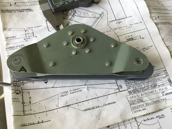
In the process of complying with the aileron hinge bracket SB on my purchased RV-6A, I happened to notice my deflections were 'not quite right', one aileron moving several degrees more than the other in total travel. I started running through the control system, and came to discover the aileron bell cranks were not manufactured according to plans.

After much thought and consultation with mechanics, community members, and the factory, I determined that, while not right, things were safe for flight. This decision was bolstered by the fact that my pink slip is twenty years old, many a conditional inspection has been performed, and many pilots have flown the aircraft and not noticed anything amiss (Other than I always thought aileron rolls one way were a bit snappy compared to the other, but figured my big fat butt in the left seat was the culprit).

I did, however, want to make things right. So I purchased the proper bell crank parts from Vans, did my first bit of building (using real rivets, not those pop-things), and found myself with two new, properly sized bell cranks.

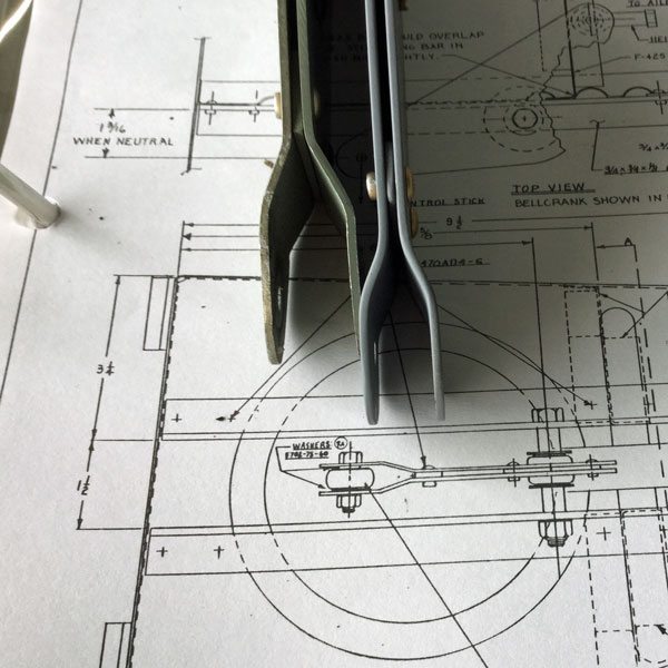
Upon returning from OSH, I went about installing these newly made parts and looking at the required changes to the rigging. Come to find out, no amount of rod end adjustment was going to get me anywhere near the installation orientation shown in the plans.

Decision time: make it work, or make it right? I do need to make a trip this weekend to check on a business venture . . .

<sigh>

Plane is down for a while, a FedEx truckload of parts (that started as two new properly sized push rods to the control stick, and ended with all new hardware end to end) is on its way across the country.

There is a responsibility that comes with the ability to perform your own maintenance, and we need to remember it is a privilege, not a right. This, I believe, is especially true for wide-eyed relatively new owners like myself who are still enamored with the incredible options available to us in the experimental community.

In the end, $300 worth of hardware and tubing is not much of a price to pay for the privilege to be able to perform my own maintenance, and in the process learn a little bit more. After all, isn't part of homebuilding education?

Guess I have a few days to start working on installing those Sam James wheel pants. Fiberglass work, Yipee! :rolleyes:
 
Last edited:
A picture is worth ...

a 1,000 words.

Hard to understand the nature of the bellcrank problem. A picture might help tremendously. However, the ailerons on the RV-6A/6 are an asymmetric system. The offset hinge pivot point is the basis for this. The number of degrees the Left aileron goes UP is not equal to the number of degrees the Right aileron goes DOWN, and vice versa. Although the relative motion in left and right action should be rigged to be mirrored. (I'm sure that's not a precise aeronautical description.)

Was one or both of the bellcranks flipped?
 
I can completely imagine how it happened, what you found, and the necessary process. I like your story of complete solution without any major drama to just fix it.
 
a 1,000 words.

Hard to understand the nature of the bellcrank problem. A picture might help tremendously. However, the ailerons on the RV-6A/6 are an asymmetric system. The offset hinge pivot point is the basis for this. The number of degrees the Left aileron goes UP is not equal to the number of degrees the Right aileron goes DOWN, and vice versa. Although the relative motion in left and right action should be rigged to be mirrored. (I'm sure that's not a precise aeronautical description.)

Was one or both of the bellcranks flipped?

Not flipped. The problem I found with the installed bell cranks was that they were symmetrical, and even then a bit short in dimension (I had seen all the discussions of making sure the long end of the bell crank was installed properly, towards the control stick). As I heard from the factory, early 90's kits like mine had these as field manufactured items from supplied stock.

Below is a picture of the old bell crank (green primer) on top of the new bell crank (gray primer) with the pivot point bearings aligned. The 'A' stands for aileron push rod attach point:

DcyoXlYl.jpg


The rigging with the old bell cranks had both sticks in the cockpit deflected left for neutral aileron, which I had not really noticed prior to this. Aileron push rods are over sized in length, according to estimates in the plans, by more than an inch. When I set control sticks to center, I found I would need another 3/4" on the control stick push rods to have the new (proper) bell cranks in the proper neutral position per the plans, and I already had the long rod end bearings installed. No bueno.

Let me say that this is in no way a criticism of the builder or any previous owner or mechanic. The plane flew fine, just the nature of what we must deal with in the experimental world.
 
Last edited:
I like that you fixed it. I hope you will post a test flight report and let us know if your plane rolls any differently now. Either way at least you know it's right now. :)
 
....As I heard from the factory, early 90's kits like mine had these as field manufactured items from supplied stock.
....

Yes, it definitely was a DIY part made from flat 0.063 stock. Getting all 8 bends to line up and have a correct, parallel gap was somewhat of a challenge. :)

They may not have been a bit short in the dimension as you say. The plans are not very explicit on whether the 3 and 3 3/8 dimensions of bolt holes to pivot are pre- or post- bending.
 
Last edited:
Great picture

The pic is excellent along with the narrative to clarify. My kit was a 1997 QB and the bellcrank components were stamped out, including the three pivot holes, and bent to form. Required only the rivets and spacers to assemble along with match drilling all rivet holes. I must have realized the asymmetry by accident when I stacked them one on top of the other. And somehow assembled them in the wing with the correct orientation.

I say that because the memory was too faded on the details. Having just gone through preliminary rigging on the wing control surfaces there was suddenly a flash of doubt raised by your pic and description. Drove to the hangar and re-checked them both ... and confirmed the 3 3/8" arm attaches to the control stick tube, and the 3" arm to the aileron. Whew!

Glad to see you fabricated the new ones. Thanks for sharing the details.
 
Yes, it definitely was a DIY part made from flat 0.063 stock. Getting all 8 bends to line up and have a correct, parallel gap was somewhat of a challenge. :)

They may not have been a bit short in the dimension as you say. The plans are not very explicit on whether the 3 and 3 3/8 dimensions of bolt holes to pivot are pre- or post- bending.


When assembled, the factory stamped, drilled (including rivet holes) and pre-bent parts were spot on in dimension between hole centers. However, the space between the parallel bends was too small to accommodate the rod end bearings, so I got to have a little bit of fun with that challenge of bending :).

Again, pivot bearings aligned, old crank with wider gap on left, unmodified new crank on right:

xkikDzTl.jpg


Before incrasing the gap size, I called builder support inquiring about the ever so slight change in distance between hole centers the geometry change would cause. They said that the slight amount of shortening was ok, no need to weld and re-drill to an exact dimension.
 
Last edited:
A simpler solution?

Remove the two end spacers and use thicker spacers to get a bigger gap for the end bearings. The spacer thickness will be a non-issue in all other dimensions accommodate the end bearings and washers. I wouldn't try to re-bend the offsets to increase the gap, a little preload to the gap is fine but it should be spaced to have parallel surfaces.
 
Last edited:
Remove the two end spacers and use thicker spacers to get a bigger gap for the end bearings. The spacer thickness will be a non-issue in all other dimensions accommodate the end bearings and washers. I wouldn't try to re-bend the offsets to increase the gap, a little preload to the gap is fine but it should be spaced to have parallel surfaces.

I disagree, if you increase the spacer thickness than the flanges that hold the rod end bearing in place will also splay out. When you pull them in they may not be parallel.

It's much easier to bend the flanges slightly and have everything square.

Also note that the flanges may or may not be sized to allow for the extra 1/8 thickness added to the rod end bearing width due to the later revision for the added small diameter washers. If you don't add these washers on at least the stick side you may have difficulty in preventing the long pushrod from binding over the full motion of stick travel.

Also, since your kit was not pre-punched make sure that the rod end bolt (shown on the plans in your second picture) has enough clearance with the angles it has to move over. Tolerances can add up in either direction - good or bad - here.
 
Last edited:
So THATS what an RV roll feels like!

Finally got the project done. Yes, a noticeable difference in both roll rate and roll onset.

Each control stick pushrod got lengthened 7/8" and the aileron pushrods got shortened 1 3/8" left, 1" right. There was quite a bit of of interference to deal with. One bearing bolt, which I fixed by adding a washer to the bolt head. And then I had to cut a LOT around the control sticks themselves, probably was limited there before and just never realized it. I should have waited until I had all the new hardware in hand before bending the flanges, as the new rod ends were slightly thinner than the old ones.

Current travel is 32/17 left, 30/15 right. I still might need a half turn or so out of the aileron rod ends to get a good neutral position in cruise, just too bumpy on the test flight to get a good look at it.

Never did get to those wheel pants . . . :rolleyes:

Mike, in one short lesson you ARE a builder. :)
 
Back
Top