boom3
Well Known Member
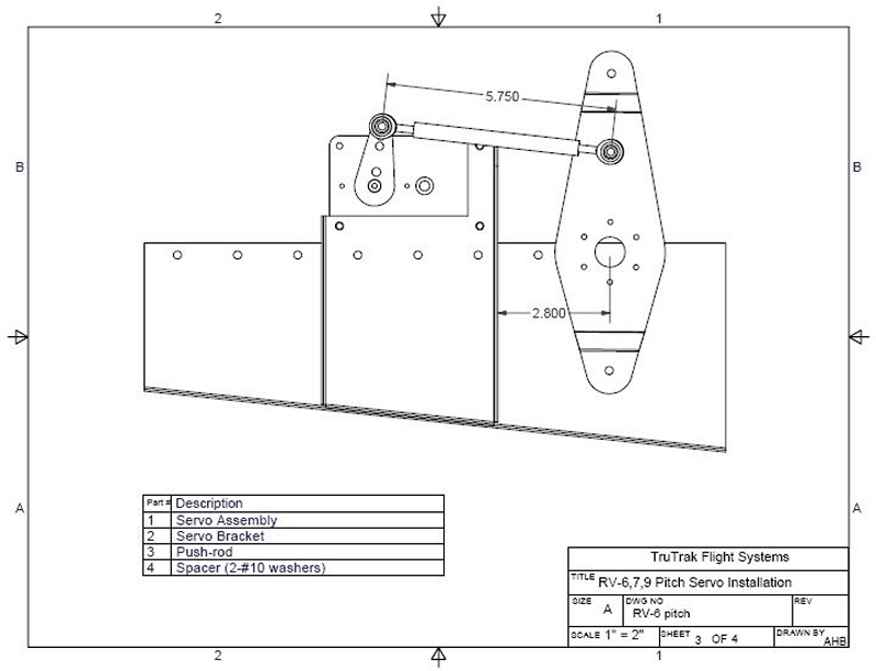
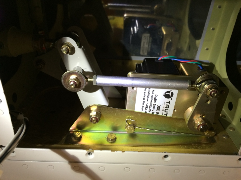
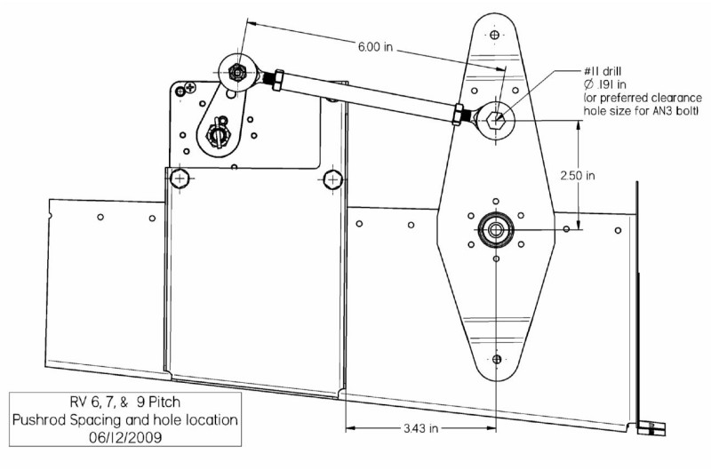
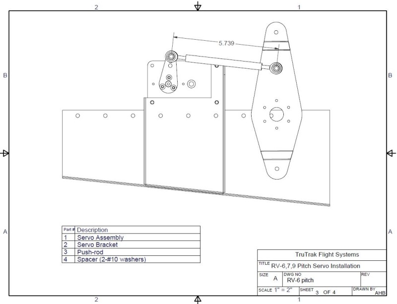
I recently ordered the Gemini AP and servos from TruTrak.  I received my servos today and although I didn't have a lot of time, I thought I'd at least see how the pitch servo fit. Years ago I installed the Dynon pitch mounting bracket while building my plane. The TruTrak bracket appears to be the same. I did notice that Dynon calls out mounting the bracket 3.43" from the center point of the bellcrank and TruTrak calls out 2.5" or something. (It's called out on the new instructions I received with the kit although it's not shown on the attached TruTrak sheet.) Also Dynon says to use a 6" push rod TruTrak says 5.739". Anyway I appear to have an issue even with the longer rod. (Picuture has 6" rod) The issue is the elevator tube hits the servo arm before the elevator hits it's "up" control stop.
Both the Dynon and TruTrak instructions show the servo arm clocked pretty close to 1 o'clock when the bellcrank is at 12 o'clock position. Is there a reason for this? I ran out of time but I'm guessing a little longer pushrod and the servo arm clocked closer to 12 might create the necessary clearance when the elevator goes up. Moving to the "center" hole on the servo arm may also do it.
Again this was just thrown together quickly as a quick "test fit" I haven't safety wired anything and the large washer on the servo arm isn't installed yet.
I figured I wouldn't bug TruTrak yet cause I know they're buried.
Any thoughts?
Dynon Install Sheet
TruTrak Install Sheet
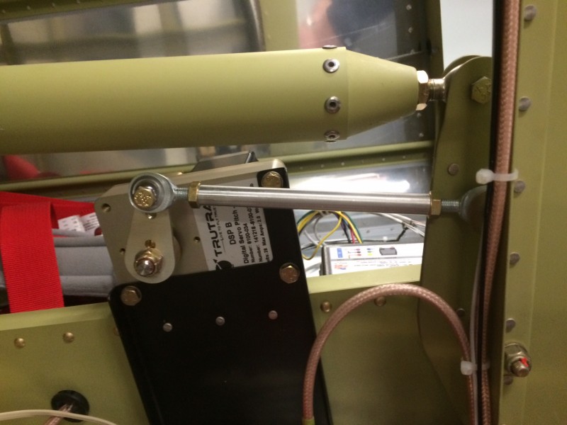
Elevator Nuetral Position
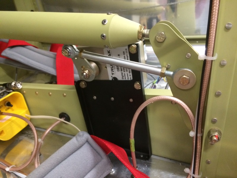
Elevator Up Position (approaching stop) Elevator tube contacts servo arm.
May need a 3rd spacing washer on the bellcrank end too as the rod comes pretty close to a rivet.
I received my servos today and although I didn't have a lot of time, I thought I'd at least see how the pitch servo fit. Years ago I installed the Dynon pitch mounting bracket while building my plane. The TruTrak bracket appears to be the same. I did notice that Dynon calls out mounting the bracket 3.43" from the center point of the bellcrank and TruTrak calls out 2.5" or something. (It's called out on the new instructions I received with the kit although it's not shown on the attached TruTrak sheet.) Also Dynon says to use a 6" push rod TruTrak says 5.739". Anyway I appear to have an issue even with the longer rod. (Picuture has 6" rod) The issue is the elevator tube hits the servo arm before the elevator hits it's "up" control stop. Both the Dynon and TruTrak instructions show the servo arm clocked pretty close to 1 o'clock when the bellcrank is at 12 o'clock position. Is there a reason for this? I ran out of time but I'm guessing a little longer pushrod and the servo arm clocked closer to 12 might create the necessary clearance when the elevator goes up. Moving to the "center" hole on the servo arm may also do it.
Again this was just thrown together quickly as a quick "test fit" I haven't safety wired anything and the large washer on the servo arm isn't installed yet.
I figured I wouldn't bug TruTrak yet cause I know they're buried.
Any thoughts?
Dynon Install Sheet
TruTrak Install Sheet
Elevator Nuetral Position
Elevator Up Position (approaching stop) Elevator tube contacts servo arm.
May need a 3rd spacing washer on the bellcrank end too as the rod comes pretty close to a rivet.